


IRF
2
5
(
n =
/
A
)
5
1
I
I
n =
/
A
( )
5
1
o
I
I
f
n =
50
60 Hz
RS 615
Ser.No.
1923
SPTO 1D2
O I
U
aux
30 ... 80 V
_
80 ... 265 V
_
R
L
SG1
1
2
0 1
I
STEP
SPAC 310 C
I
I
L1
L2
L3
[kA]
[kA]
[kA]
O
I
TEST
INTERLOCK
[MW]
[Mvar]
[GWh, MWh, kWh]
P
Q
E
RS 232
GAS PRESSURE
MOTOR VOLTAGE
[
SGR
SGB
SGF
SPCJ 4D29
TRIP
PROGRAM
RESET
STEP
L1
L2
L3
o
IRF
3
>
I
I
I
I
I
I
>
n
I
I
/
k
s
>
t
]
n
>>
I
I
/
s
>>
[ ]
t
s
o >
k o
[ ]
t
n
o >
I
I
/
s
>>
o
t
[ ]
n
>>
o
I
/
I
0012A
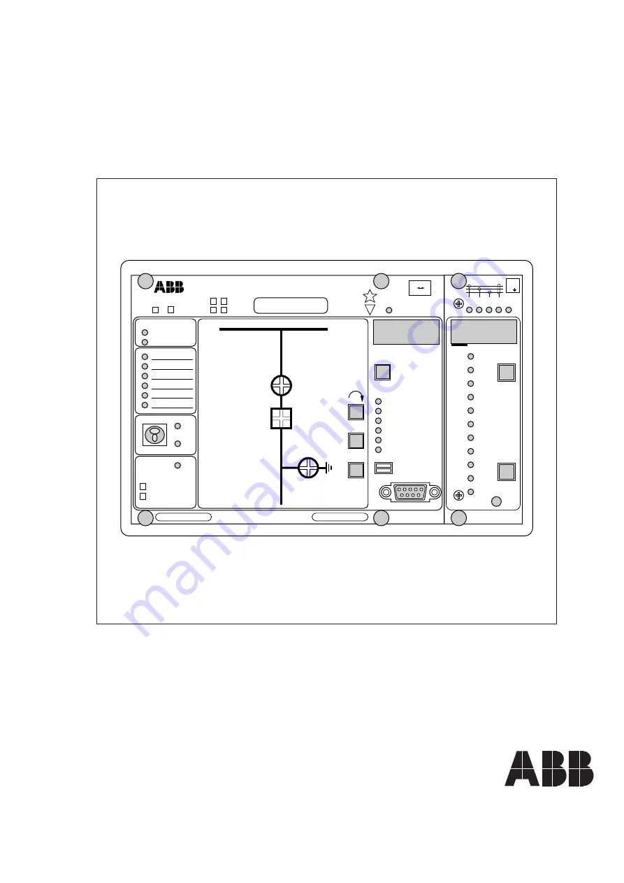
SPAC 310 C and SPAC 312 C
Feeder Terminal
User´s manual and Technical description


