background image

Relion

®

 650 series

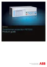
Transformer protection RET650

Product guide

Summary of Contents for ret650

Page 1: ...Relion 650 series Transformer protection RET650 Product guide...

Page 2: ...rdering for Customized IED 60 21 Ordering for Configured IED 64 22 Ordering for Accessories 66 Disclaimer The information in this document is subject to change without notice and should not be constru...

Page 3: ...r ratio matching and vector group compensation makes this IED the ideal solution even for the most demanding applications Since RET650 has very low requirements on the main CTs no interposing CTs are...

Page 4: ...nfigured functions REF PDIF 87N IdN I EF4 PTOC 51N 67N IN DRP RDRE Mont Y Y P ROV2 PTOV 59N 3U0 RET650 A01 2 Winding Transformer protection 10AI 8I 2U 20 MVA 110 11 1 5 21 kV 105 550 A YNd5 20 kV Bus...

Page 5: ...50 3I TR PTTR 49 Ith REF PDIF 87N IdN I Other configured functions REF PDIF 87N IdN I REF PDIF 87N IdN I OEX PVPH 24 U f OC4 PTOC 51 67 3I EF4 PTOC 51N 67N IN EF4 PTOC 51N 67N IN DRP RDRE Mont CV MMX...

Page 6: ...CM YLTC 84 TCM YLTC 84 TCS SCBR Cond TCS SCBR Cond SPVN ZBAT Cond Other configured functions DRP RDRE Mont T1 Data 20 MVA 110 11 1 5 21 kV 105 550 A YNd5 XT 11 T2 Data 20 MVA 110 11 1 5 21 kV 105 550...

Page 7: ...winding 0 1 1 T3WPDIF 87T Transformer differential protection three winding 0 1 1 REFPDIF 87N Restricted earth fault protection low impedance 0 3 2 3 HZPDIF 87 1Ph High impedance differential protect...

Page 8: ...50BF Breaker failure protection 3 phase activation and output 0 3 2 3 CCRPLD 52PD Pole discordance protection 0 3 2 3 GUPPDUP 37 Directional underpower protection 0 2 1 1 2 GOPPDOP 32 Directional ove...

Page 9: ...ommands generic for IEC60870 5 103 50 50 50 50 I103POSCMD IED commands with position and select for IEC60870 5 103 50 50 50 50 Apparatus control and Interlocking APC8 Apparatus control for single bay...

Page 10: ...figurable logic blocks Q T 0 12 INDCOMBSPQT Configurable logic blocks Q T 0 20 INDEXTSPQT Configurable logic blocks Q T 0 20 FXDSIGN Fixed signal function block 1 1 1 1 B16I Boolean 16 to Integer conv...

Page 11: ...6 inputs 16 16 16 16 MVGGIO IEC 61850 generic communication I O functions 16 16 16 16 MVEXP Measured value expander block 66 66 66 66 SPVNZBAT Station battery supervision 0 1 1 1 1 SSIMG 63 Insulation...

Page 12: ...1 1 1 1 RS485GEN RS485 1 1 1 1 OPTICALPROT Operation selection for optical serial 1 1 1 1 RS485PROT Operation selection for RS485 1 1 1 1 DNPFREC DNP3 0 fault records for TCP IP communication protoco...

Page 13: ...sion with internal event list 1 TIMESYNCHGEN Time synchronization 1 SNTP Time synchronization 1 DTSBEGIN DTSEND TIMEZONE Time synchronization daylight saving 1 IRIG B Time synchronization 1 SETGRPS Se...

Page 14: ...d on all directly or low impedance earthed windings The REFPDIF function provides high sensitivity and high speed tripping as it protects each winding separately and thus does not need inrush stabiliz...

Page 15: ...equence direction EF4PTOC The four step residual overcurrent protection zero or negative sequence direction EF4PTOC has a settable inverse or definite time delay independent for step 1 and 4 separatel...

Page 16: ...ction of power lines where incorrect zero sequence polarization may result from mutual induction between two or more parallel lines Additionally it is applied in applications on cables where zero sequ...

Page 17: ...of the fuse failure supervision function SDDRFUF is to block voltage measuring functions at failures in the secondary circuits between the voltage transformer and the IED in order to avoid inadvertent...

Page 18: ...e 8 switch controllers SCSWI may handle and operate on one three phase apparatus Each of the 3 circuit breaker controllers SXCBR provides the actual position status and pass the commands to the primar...

Page 19: ...permitted to operate due to actual switchyard topology The interlocking conditions are generated in separate function blocks containing the interlocking logic SCSWI The Switch controller initializes...

Page 20: ...delay and must be On for the input signal to activate the output with the appropriate time delay AND function block Each block has four inputs and two outputs where one is inverted SRMEMORY function b...

Page 21: ...s Integer to Boolean 16 conversion with logic node representation IB16FCVB Integer to boolean conversion with logic node representation function IB16FCVB is used to transform an integer to 16 binary l...

Page 22: ...tatus during a disturbance Event recorder DRPRDRE Quick complete and reliable information about disturbances in the primary and or in the secondary system is vital for example time tagged events logge...

Page 23: ...ion generates alarms based on received information Circuit breaker monitoring SSCBR The circuit breaker condition monitoring function SSCBR is used to monitor different parameters of the circuit break...

Page 24: ...s in a highly adaptable IED that can be applied to a variety of power system scenarios Test mode functionality TESTMODE The protection and control IEDs may have many included functions To make the tes...

Page 25: ...P3 It is possible to map respective protocol to the signals of interest and configure them for monitoring with the Communication Management tool CMT in PCM600 No events are mapped by default Parameter...

Page 26: ...cate data between components in process automation systems For a detailed description of the DNP3 protocol see the DNP3 Communication protocol manual IEC 60870 5 103 communication protocol IEC 60870 5...

Page 27: ...ordering for details about available mounting alternatives Rack mounting a single 3U IED B A C D IEC11000248 V1 EN Figure 11 Rack mounted 3U IED A 224 mm 12 mm with ring lug connectors B 22 5 mm C 48...

Page 28: ...ttp www abb com substationautomation Connection diagrams for Customized products Connection diagram 650 series 1 3 1MRK006501 AD Connection diagrams for Configured products Connection diagram RET650 1...

Page 29: ...this document are only valid under the following circumstances CT and VT ratios in the IED are set in accordance with the associated main instrument transformers Note that for functions which measure...

Page 30: ...mic withstand 250 A one half wave 1250 A one half wave Burden 1 mVA at Ir 0 1 A 10 mVA at Ir 1 A 20 mVA at Ir 0 5 A 200 mVA at Ir 5 A max 350 A for 1 s when COMBITEST test switch is included Voltage i...

Page 31: ...in PSM module 1 bit represents 0 5 V 1 VDC 1 bit represents 1 V 1 VDC 1 bit represents 2 V 1 VDC Binary inputs and outputs Table 4 Binary inputs Description Value Operating range Maximum input voltag...

Page 32: ...er the TCS contact 20 V DC Table 8 Ethernet interfaces Ethernet interface Protocol Cable Data transfer rate 100BASE TX CAT 6 S FTP or better 100 MBits s 100BASE FX TCP IP protocol Fibre optic cable wi...

Page 33: ...ded Table 13 Serial rear interface Type Counter connector Serial port X9 Optical serial port type ST for IEC 60870 5 103 and DNP serial Table 14 Optical serial port X9 Wave length Fibre type Connector...

Page 34: ...nsport and storage temperature range 40 85 C Table 17 Environmental tests Description Type test value Reference Cold tests operation storage 96 h at 25 C 16 h at 40 C 96 h at 40 C IEC 60068 2 1 ANSI C...

Page 35: ...4 4 IEC 60255 22 4 class A ANSI C37 90 1 2012 Communication ports 4 kV Other ports 4 kV Surge immunity test IEC 61000 4 5 IEC 60255 22 5 Communication 1 kV line to earth Other ports 2 kV line to earth...

Page 36: ...IEC 30 230 MHz 40 dB V m quasi peak measured at 10 m distance 230 1000 MHz 47 dB V m quasi peak measured at 10 m distance Table 19 Insulation tests Description Type test value Reference Dielectric tes...

Page 37: ...hstand test IEC 60255 21 2 Class 1 Bump test IEC 60255 21 2 Class 1 Seismic test IEC 60255 21 3 Class 2 Product safety Table 21 Product safety Description Reference LV directive 2006 95 EC Standard EN...

Page 38: ...ically at 0 to 5 x set level Reset time restrained function 25 ms typically at 5 to 0 x set level Operate time unrestrained function 20 ms typically at 0 to 5 x set level Reset time unrestrained funct...

Page 39: ...400 V I U R 1 0 of Ir Reset ratio 95 Maximum continuous power U Trip2 SeriesResistor 200 W Operate time 10 ms typically at 0 to 10 x Ud Reset time 100 ms typically at 10 to 0 x Ud Critical impulse ti...

Page 40: ...5 3000 000 phase 2 0 static accuracy Conditions Voltage range 0 1 1 1 x Ur Current range 0 5 30 x Ir Angle at 85 degrees Reverse positive sequence impedance 0 005 3000 000 phase Angle for positive seq...

Page 41: ...n operating current 5 10000 of lBase 1 0 of Ir at I Ir 1 0 of I at I Ir 2nd harmonic blocking 5 100 of fundamental 2 0 of Ir Independent time delay 0 000 60 000 s 0 5 25 ms Minimum operate time for in...

Page 42: ...ime 20 ms typically at 0 to 2 x Iset Reset time 30 ms typically at 2 to 0 x Iset Critical impulse time 10 ms typically at 0 to 2 x Iset Operate time 10 ms typically at 0 to 5x Iset Reset time 40 ms ty...

Page 43: ...Minimum polarizing voltage Zero sequence 1 100 of UBase 0 5 of Ur Minimum polarizing voltage Negative sequence 1 100 of UBase 0 5 of Ur Minimum polarizing current Zero sequence 2 100 of IBase 1 0 of...

Page 44: ...er failure protection 3 phase activation and output CCRBRF Function Range or value Accuracy Operate phase current 5 200 of lBase 1 0 of Ir at I Ir 1 0 of I at I Ir Reset ratio phase current 95 Operate...

Page 45: ...oltage level 0 0 5 0 of UBase 0 5 of Ur Relay characteristic angle 180 180 degrees 2 0 degrees Relay operate angle 1 90 degrees 2 0 degrees Timers 0 00 6000 00 s 0 5 25 ms Operate time non directional...

Page 46: ...s typically at 1 2 to 0 8 x Uset Impulse margin time 15 ms typically Table 39 Two step overvoltage protection OV2PTOV Function Range or value Accuracy Operate voltage step 1 and 2 1 200 of UBase 0 5 o...

Page 47: ...art function 30 ms typically at 0 to 2 x Uset Reset time start function 40 ms typically at 2 to 0 x Uset Critical impulse time 10 ms typically at 0 to 1 2 xUset Impulse margin time 15 ms typically Tab...

Page 48: ...3 Overfrequency protection SAPTOF Function Range or value Accuracy Operate value start function 35 00 75 00 Hz 2 0 mHz at symmetrical three phase voltage Reset ratio 0 999 Operate time start function...

Page 49: ...Ir Operate voltage change level 1 100 of UBase 5 0 of Ur Operate current change level 1 100 of IBase 5 0 of Ir Operate phase voltage 1 100 of UBase 0 5 of Ur Operate phase current 1 100 of IBase 1 0 o...

Page 50: ...5 0 of set value Overcurrent block level 0 250 of IBase 1 0 of Ir at I Ir 1 0 of I at I Ir Level for number of counted raise lower within one hour 0 30 operations hour Level for number of counted rai...

Page 51: ...me Range or value Accuracy 20 ms 100 ms ANDQT 20 100 ORQT 20 100 XORQT 10 30 INVERTERQT 20 100 RSMEMORYQT 10 30 SRMEMORYQT 15 10 PULSETIMERQT 10 30 0 000 90000 000 s 0 5 25 ms for 20 ms cycle time TIM...

Page 52: ...1 0 of Sr at S Sr 1 0 of S at S Sr Apparent power S 0 1 x Ur U 1 5 x Ur 0 2 x Ir I 4 0 x Ir 1 0 of Sr at S Sr 1 0 of S at S Sr Apparent power S Three phase settings cos phi 1 0 5 of S at S Sr 0 5 of...

Page 53: ...report 96 Maximum number of events in the Event recording per recording 150 Maximum number of events in the Event list 1000 first in first out Maximum total recording time 3 4 s recording time and ma...

Page 54: ...maximum number of channels typical value 340 seconds 100 recordings at 50 Hz 280 seconds 80 recordings at 60 Hz Table 61 Station battery supervision SPVNZBAT Function Range or value Accuracy Lower lim...

Page 55: ...alarm 0 00 60 00 s 0 5 25 ms Time delay for gas pressure lockout 0 00 60 00 s 0 5 25 ms Metering Table 65 Pulse counter PCGGIO Function Setting range Accuracy Cycle time for report of counter value 1...

Page 56: ...r the IEDs 100BASE FX Protocol serial IEC 60870 5 103 Communication speed for the IEDs 9600 or 19200 Bd Protocol serial DNP3 0 Communication speed for the IEDs 300 115200 Bd Hardware IED Dimensions Ta...

Page 57: ...Very Inverse A 28 55 B 0 712 P 2 0 ANSI Long Time Inverse A 0 086 B 0 185 P 0 02 Table 70 IEC Inverse time characteristics Function Range or value Accuracy Operating characteristic 1 P A t k I EQUATI...

Page 58: ...set k 0 05 999 in steps of 0 01 Table 72 Inverse time characteristics for overvoltage protection Function Range or value Accuracy Type A curve t k U U U EQUATION1436 SMALL V1 EN U Uset U Umeasured k 0...

Page 59: ...0 in steps of 0 01 Table 74 Inverse time characteristics for residual overvoltage protection Function Range or value Accuracy Type A curve t k U U U EQUATION1436 SMALL V1 EN U Uset U Umeasured k 0 05...

Page 60: ...upply module Rule One Power supply module must be specified Power supply module PSM01 24 30V DC 9BO 1KHL178029R0001 PSM02 48 125V DC 9BO 1KHL178073R0001 PSM03 110 250V DC 100 240V AC 9BO 1KHL178082R00...

Page 61: ...3 1MRK 004 908 AA Four step phase overcurrent protection 3 phase output OC4PTOC Qty 1 2 3 1MRK 004 908 BC Instantaneous residual overcurrent protection EFPIOC Qty 1 2 3 1MRK 004 908 CA Four step resi...

Page 62: ...C8 Qty 1MRK 004 917 GA Circuit breaker for 2 CB CBC2 Qty 1MRK 004 918 BA Circuit breaker for 3 CB CBC3 Qty 1MRK 004 918 CA Circuit breaker for 4 CB CBC4 Qty 1MRK 004 918 DA Automatic voltage control f...

Page 63: ...Qty 1KHL178083R0013 Transformer module TRM01 4I 1 5A 1I 0 1 0 5A 5U 100 220V 50 60Hz Qty 1KHL178083R0016 Transformer module TRM01 4I 1 5A 6U 100 220V 50 60Hz Qty 1KHL178083R0003 Rule Only one Analog...

Page 64: ...3 Selection for position 1 1 3 Configuration alternatives 2 Notes and Rules Single breaker 2 winding A01 Single breaker 3 winding A05 Tap changer control A07 ACT configuration ABB standard configurat...

Page 65: ...module TRM01 8I 1 5A 2U 100 220V 50 60Hz A2 Basic in A01 Slot position p4 Analog input module AIM01 6I 1 5A 4U 100 220V 50 60Hz B1 Only in A05 Selection for position 9 Binary input output module 10 No...

Page 66: ...l special paper Letter 1 pc Quantity 1MRK 002 038 DA Manuals Note One 1 IED Connect DVD containing user documentation Operation manual Technical manual Installation manual Commissioning manual Applica...

Page 67: ...ity 1MRK 511 281 UEN Communication protocol manual IEC 60870 5 103 IEC Quantity 1MRK 511 282 UEN Engineering manual IEC Quantity 1MRK 511 284 UEN Installation manual IEC Quantity 1MRK 514 016 UEN Poin...

Page 68: ...nication protocol manual DNP 3 0 1MRK 511 280 UEN Communication protocol manual IEC 61850 8 1 1MRK 511 281 UEN Communication protocol manual IEC 60870 5 103 1MRK 511 282 UEN Cyber Security deployment...

Page 69: ...69...

Page 70: ...ce ABB AB does not accept any responsibility whatsoever for potential errors or possible lack of information in this document We reserve all rights in this document and in the subject matter and illus...

Reviews: