ABB REM 610, Operator'S Manual
The ABB REM 610 product manual is available for free download from our website. This comprehensive manual provides essential information on operating and maintaining the REM 610, ensuring smooth and efficient performance. Get your free copy today at manualshive.com and unleash the full potential of your device.
Share
Download


Reviews:
No comments
Related manuals for REM 610

TI 180 E
Brand: Danfoss Pages: 32

BR-11
Brand: Mart Pages: 4

EXT10000084
Brand: Zamel Pages: 2

Allen-Bradley 700-SA
Brand: Rockwell Automation Pages: 69
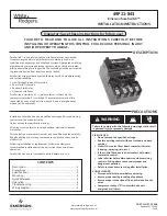
White Rogers SureSwitch 49P11-843
Brand: Emerson Pages: 12

Liebert IntelliSlot IS-RELAY
Brand: Emerson Pages: 8

Alco Controls PS4 Series
Brand: Emerson Pages: 2

M?3311A
Brand: BECKWITH ELECTRIC Pages: 450

4028682
Brand: Malmbergs Pages: 2

ecomat 200 Monitor AL-3
Brand: IFM Electronic Pages: 64

111016
Brand: Eaton Pages: 16

D30
Brand: FANOX Pages: 2

SIA C Series
Brand: FANOX Pages: 32

BIS-411 1R1Z
Brand: F&F Pages: 6

HFA151
Brand: GE Pages: 16

PCP series
Brand: macromatic Pages: 2

CSR-112
Brand: Greystone Pages: 2

KD-10
Brand: ABB Pages: 56


