ABB REL 301, Instruction Leaflet
The ABB REL 301 Instruction Leaflet is a comprehensive and user-friendly manual for effortless operation and setup. Easily downloadable and absolutely free, you can access this invaluable resource from manualshive.com. Get the most out of your ABB REL 301 with step-by-step instructions and troubleshooting guidance, ensuring optimal performance.
Share
Download


Reviews:
No comments
Related manuals for REL 301

SNO 1012K
Brand: Wieland Pages: 32

P1HZ 2
Brand: Pilz Pages: 16

RGM-12S
Brand: Tense Pages: 26

ICR51A
Brand: GE Pages: 16

IAV54E
Brand: GE Pages: 32

IBCG51E21
Brand: GE Pages: 16

IFC51A AND 518
Brand: GE Pages: 36

IBCG51M
Brand: GE Pages: 50

P741
Brand: GE Pages: 560

IFC66CD
Brand: GE Pages: 2

JR-2
Brand: M.C. MILLER Pages: 27

BASICR3
Brand: Sonoff Pages: 52

REL 301
Brand: ABB Pages: 132

EDR-5000
Brand: Eaton Pages: 4

Relay
Brand: AJAX Systems Pages: 11

K8AB-AS
Brand: Omron Pages: 12
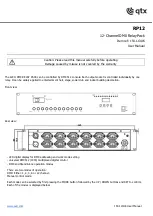
RP12
Brand: Qtx Pages: 4

RadioLink AccentPoint Relay Station II APREL
Brand: Vantage Hearth Pages: 2


