A-TS TECHNOLOGY RT20, Руководство пользователя
"A-TS TECHNOLOGY RT20" - это продукт высоких технологий с инновационными возможностями. Пользователь может загрузить бесплатное руководство на русском языке с ключевыми словами "User Manual", "manual", "download" на manualshive.com. Изучите все функции этого продукта для оптимального использования.
Поделиться
Скачать


Отзывы:
Нет отзывов
Похожие инструкции для RT20

KA 66-TW-K
Бренд: D+H Страницы: 16

Easy Drive CFW10
Бренд: WEG Страницы: 2

GPD 315
Бренд: Magnetek Страницы: 119

+Q957
Бренд: ABB Страницы: 20

1400
Бренд: Eskridge Страницы: 7

E1
Бренд: Aqara Страницы: 132

VLT Midi Drive FC 280
Бренд: Danfoss Страницы: 92

SI-P1/ V7
Бренд: YASKAWA Страницы: 9

900-00008
Бренд: Parallax Страницы: 8

MC-D-250-1000-050W-TW
Бренд: Unex Страницы: 2

M81135
Бренд: Raymarine Страницы: 17
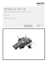
Rexroth MOBILEX GFT-W 30 Series
Бренд: Bosch Страницы: 86

Rexroth Sytronix SvP 7020 PFC
Бренд: Bosch Страницы: 76

Sonesse 30 RS485
Бренд: SOMFY Страницы: 16

Orea 50 WT
Бренд: SOMFY Страницы: 8

Breeze-com SE 2/10
Бренд: Selve Страницы: 152

PWM3D-000
Бренд: ALTER Страницы: 88


