3onedata IEM615 Series, Hardware User Manual
Discover the robust capabilities of the 3onedata IEM615 Series in the comprehensive Hardware User Manual. This guide is essential for maximizing your device's performance. Download the free manual directly from manualshive.com to ensure easy setup and troubleshooting. Ideal for industrial network management, get your copy today!
Share
Download


Reviews:
No comments
Related manuals for IEM615 Series
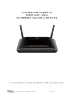
DSL-2740B
Brand: D-Link Pages: 10

3C410012A - OfficeConnect Remote 531 Access...
Brand: 3Com Pages: 72

Storagelibrary T24
Brand: Tandberg Data Pages: 28

Magic WiFi mini Ek
Brand: Devolo Pages: 22

SUPERLOADER DLT MAGAZINE
Brand: Tandberg Data Pages: 6

FWA8207 Series
Brand: IBASE Technology Pages: 39

XGS4600 Series
Brand: ZyXEL Communications Pages: 645

NR-2008
Brand: Brickcom Pages: 184

CVN-0430F
Brand: Commax Pages: 122

Router 3000 Series
Brand: 3Com Pages: 37

N304-05M
Brand: Tripp Lite Pages: 2

BiPAC 7820NZ
Brand: Billion Pages: 100

TransPort WR11 XT
Brand: Digi Pages: 4

SYRD245-1N
Brand: Syris Pages: 27

ITI-2135
Brand: IntraServer Technology Pages: 16

C190
Brand: Cisco Pages: 14

Vega 50 FXS
Brand: VegaStream Pages: 41

NVR-7072
Brand: Swann Pages: 30


