background image

1

Important Safety Information

Intended Use

GRINDERS, TYPE-27 INSTRUCTION MANUAL

101 mm (4 in.) - 113 mm (4 1/2 in.)

12,000 RPM

Please read, understand and follow all safety information contained in these instructions prior to the use of this tool.
Retain these instructions for future reference.

These pneumatic tools are intended for use in industrial locations, and used only by skilled, trained professionals in accordance with the instructions in this 

manual. These pneumatic tools are designed to be used with the appropriate size Type 27 Wheel for grinding metals. They should only be used for such grinding 

applications and within their marked capacity and ratings. Only accessories specifically recommended by 3M should be used with these tools. Use in any other 

manner or with other accessories could lead to unsafe operating conditions. 

Do not operate tool in water or in an excessively wet application. 

Do not use grinding wheels that have a Max RPM less than the marked RPM rating on the tool.

To reduce the risks associated with impact from abrasive product or tool breakup, sharp edges, hazardous pressure, rupture, vibration and noise:

•  Read, understand and follow the safety information contained in these instructions prior to the use of this tool. Retain these instructions for future reference.
•  Only personnel who are properly trained should be allowed to service this tool.
•  Practice safety requirements. Work alert, have proper attire, and do not operate tools under the influence of alcohol or drugs.
•  Operators and other personnel must always wear protection for eyes, ears, and respiratory protection when in the work area or while operating this 

product. Follow your employer’s safety policy for PPE’s and/or ANSI Z87.1 or local/national standards for eyewear and other personal protective equipment 
requirements.

•  Wear leather apron or other protective apparel, taking into consideration the type of work being done.
•  Never exceed marked maximum input pressure (90psi / .62Mpa / 6.2Bars).
•  Proper eye protection must be worn at all times.
•  Tool is not to be operated in the presence of bystanders.
•  If you notice any abnormal noise or vibration when operating the product, immediately discontinue its use and inspect for worn or damaged abrasive 

product or accessories. Correct or replace the suspect component. If abnormal noise or vibration still exists, return the tool to 3M for repair or replacement. 
Refer to warranty instructions.

•  Never operate this tool without all guards or safety features in place and in proper working order.
•  Prior to use, ensure guard is oriented to protect the operator from flying fragments and is properly secured.
•  Make sure the tool is disconnected from its air source before servicing, inspecting, maintaining, cleaning, and before changing abrasive product.
•  Only use wheel retainers (flanges) and wheel arbors supplied by 3M.
•  Never use this tool with Type 1 wheels or cut-off wheels.

WARNING

Original Instructions

Rev. 2/19/2015

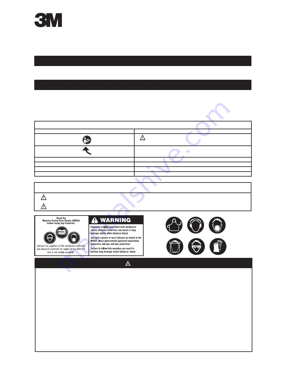
Summary of device labels containing safety information

Marking

Description

 WARNING:

 Refer to Instruction Manual

Direction of Rotation

90psi / .62Mpa / 6.2Bars Max

Maximum Pneumatic Inlet Pressure

12,000 RPM

Maximum Rotational Speed

Use accessories rated at tool RPM or higher

Accessories Safety Note

Prolonged vibration may cause injury

Vibration Safety Note

Explanation of Signal Word Consequences

Indicates a potentially hazardous situation which, if not avoided, may result in death or serious injury and/or property damage.

Indicates a potentially hazardous situation which, if not avoided, may result in minor or moderate injury and/or property damage.

WARNING:

CAUTION:

Summary of Contents for TYPE-27

Page 1: ... and or ANSI Z87 1 or local national standards for eyewear and other personal protective equipment requirements Wear leather apron or other protective apparel taking into consideration the type of work being done Never exceed marked maximum input pressure 90psi 62Mpa 6 2Bars Proper eye protection must be worn at all times Tool is not to be operated in the presence of bystanders If you notice any a...

Page 2: ...e the risks associated with loud noise Always wear hearing protection while operating this tool Follow your employer s safety policy or local national standards for personal protective equipment requirements To reduce the risks associated with fire or explosion Do not operate the tool in explosive atmospheres such as in the presence of flammable liquids gases or dust The abrasives are able to crea...

Page 3: ...Handle 3 8 16 EXT Thread 3M PN28402 1 15 06653 Angle Head Clamp Nut 1 16 06655 Lock Ring 1 17 06520 Pin 1 8 x 1 4 1 18 06609 O Ring 1 19 06510 Ball Bearing 3 8 x 7 8 x 9 32 1 20 06639 Front End Plate 1 21 06562 Rotor 1 22 06643 Vane Set of 5 1 23 06563 Cylinder 1 24 06560 Rear End Plate 1 25 06527 Wave Washer 440 x 618 x 008 1 26 06508 Ball Bearing 1 Fig 3M PN Description Qty 27 06567 Washer 251 x...

Page 4: ...3 8 16 EXT Thread 3M PN28402 1 14 06653 Angle Head Clamp Nut 1 15 06655 Lock Ring 1 16 06520 Pin 1 8 x 1 4 1 17 06609 O Ring 1 18 06510 Ball Bearing 3 8 x 7 8 x 9 32 1 19 06639 Front End Plate 1 20 06562 Rotor 1 21 06643 Vane Set of 5 1 22 06563 Cylinder 1 23 06560 Rear End Plate 1 24 06527 Wave Washer 440 x 618 x 008 1 Fig 3M PN Description Qty 25 06508 Ball Bearing 1 26 06567 Washer 251 x 468 x ...

Page 5: ...ng 36 06567 Washer 37 06568 Button Head Cap Screw 8 32 x 3 8 in 38 55099 Housing 39 06642 Lever Assembly 40 06558 Pin Torr 3 16 in x 7 8 in 41 06543 O Ring 42 06511 O Ring 1 16 in x 3 8 in x 1 2 in 43 06556 Regulator 44 06501 Set Screw 6 32 x 3 4 in 45 06559 Knurl Pin 46 06598 Housing Cover 47 06566 Warning Label 48 06552 Throttle Valve Seat 49 06557 Muffler 50 06553 Throttle Valve 51 06554 Taper ...

Page 6: ... Ball Bearing 35 06567 Washer 36 06568 Button Head Cap Screw 8 32 x 3 8 in 37 06638 Housing 38 06642 Lever Assembly 39 06558 Pin Torr 3 16 in x 7 8 in 40 06543 O Ring 41 06511 O Ring 1 16 in x 3 8 in x 1 2 in 42 06556 Regulator 43 06501 Set Screw 6 32 x 3 4 in 44 06559 Knurl Pin 45 06598 Housing Cover 46 06566 Warning Label 47 06552 Throttle Valve Seat 48 06557 Muffler 49 06553 Throttle Valve 50 0...

Page 7: ... tool can be run at lower pressures but should never be run higher than 6 2 bar 90 psig If run at lower pressure the performance of the tool is reduced Recommended Airline Recommended Maximum Air Pressure Size Minimum Hose Length 10 mm 3 8 in 8 meters 25 feet Maximum Working Pressure 6 2 bar 90 psig 12 7 mm 1 2 in Recommended Minimum NA NA Declared noise levels measurements carried out in accordan...

Page 8: ...recommended 13 Prior to installing any abrasive grinding wheel always check that its marked maximum operating speed is equal or higher than the rated speed of this tool 14 The tool is not electrically insulated Do not use where there is a possibility of contact with live electricity gas pipes and or water pipes 15 Take care to avoid entanglement with the moving parts of the tool with clothing ties...

Page 9: ...read 5 8 11 EXT M10 1 25 INT Fibre Disc Mounting Accessories 3M PN UPC PN Description Size in 28442 28442 Disc Pad Hub For Short Shaft Tools 2 1 2 x 3 8 24 INT 28476 28476 Low Profile Disc Pad Hub 2 1 2 x 5 8 11 INT 28443 28443 Disc Pad Face Plate Ribbed Extra Hard Red 4 1 2 3M Fibre Discs and Accessories 3M Disc Pad Accessories Related Products Refer to ANSI B7 1 2000 Safety Requirements for Use ...

Page 10: ...28413 can accomodate an adapter to change the spindle to a 5 8 11 threads per inch spindle to allow the use of wheels with either 16 mm or 7 8 center holes CH Refer to ANSI B7 1 2000 Safety Requirements for Use Care and Protection of Abrasive Wheels and ISO EN 12413 Safety Requirements for Bonded Abrasive Products for proper abrasive wheel applications MOUNTING 3 8 CENTER HOLE TYPE 27 WHEELS Figur...

Page 11: ...Figure 6A Figure 6B Figure 7 Figure 8 5 8 11 threads per inch Spindle with Upper Flange properly mounted For Wheels less than 3 8 thick Lower Flange for 7 8 Type 27 Wheels properly mounted For Wheels 3 8 thick and Greater Lower Flange for Type 27 7 8 Center Hole Wheels Note 7 8 lip is facing the wheel Dual Size Flanges for 16 mm and 7 8 CH Wheels Side A 16 mm lip Side B 7 8 lip 7 8 lip 3 8 24 Spin...

Page 12: ...ce Plate Figure 11 Figure 12 Figure 13 Figure 9 Figure 10 Hubs for Fibre Disc Mounting 3M PN 28442 Disc Pad Hub for Short Shaft Tools 3 8 24 INT 5 8 11 EXT 3M PN 28476 Low Profile Disc Pad Hub 5 8 11 INT Type 27 Wheel with 7 8 CH properly mounted to Upper Dual Size Flange Dual Size Lower Flange properly mounted with 7 8 CH Type 27 Wheel 5 8 11 Threads per inch Spindle 3M PN 28476 Low Profile Disc ...

Page 13: ...Nut is not required if a TN Quick Change disc is mounted Figure 16 Figure 17 Figure 18 Figure 14 Figure 15 3M PN 28442 Disc Pad Hub for Short Shaft Tools 3 8 24 INT 5 8 11 EXT NOTE 3 8 24 Tool Spindle Inside 5 8 11 Hub Spindle 3M PN 02618 Disc Retainer Nut 5 16 x 5 8 11 INT Fibre Disc with TH Quick Change Center 5 8 11 INT TN Quick Change Disc properly mounted Disc Retainer Nut properly mounted Di...

Page 14: ...art that fails due to normal wear inadequate or improper maintenance inadequate cleaning non lubrication improper operating environment improper utilities operator error or misuse alteration or modification mishandling lack of reasonable care or due to any accidental cause If a tool or any part thereof is defective within this warranty period your exclusive remedy and 3M s sole obligation will be ...

Reviews: