FV1116 Rev. C 7/19/18
Page 2
1
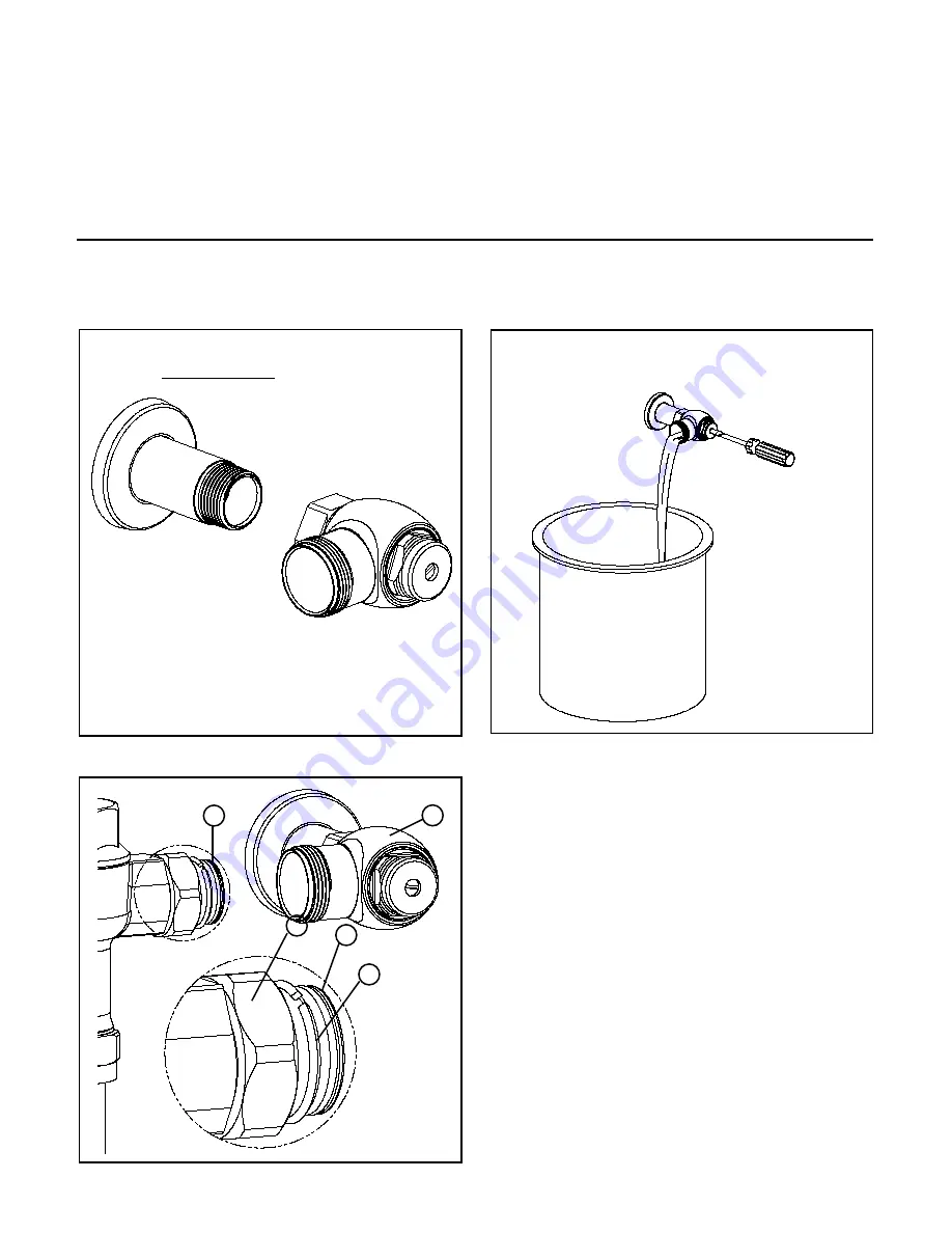
1. Install stop valve assembly using sweat solder adapter
kit if applicable. Thread sealing compounds should be
used on male NPT threads only.
2.)
Before the supply water is turned on, be sure all stop valves
are closed off tight. The stop valves can be opened and
closed by using the adjusting screw located at the center
of the stop valve cap. Stop valve adjustments can only be
made by using the adjusting screw.
It is not necessary to
remove the stop valve cap when making adjustments.
If for any reason it becomes necessary to remove the
stop valve cap, be certain the water is shut off at the
main supply valve.
3.)
Prior to inserting the flush valve tailpiece
(B)
into stop valve
(A)
, be certain that the O-ring seal
(C)
is located in O-ring
seal groove at the end of the tailpiece and that the locking
nut
(D)
and locking snap ring
(E)
are located as shown. Care
should be taken not to damage the O-ring when inserting the
tailpiece into the stop valve. If lubrication is needed, wetting
the O-ring with water will be sufficient.
4.)
Insert the flush valve tailpiece
(B)
into the stop valve
(A)
and hand tighten the lock nut
(D)
to the stop valve. Level
the entire unit.
When all stop(s) are connected to the water supply and
water pressure is available, flush the supply piping to
remove dirt, metal chips, etc., from system.
A. Before the valve is installed, open each stop fully for a
brief time and catch the water in a two gallon or larger
bucket. For multiple installations, start with the stop
valve closest to
the water supply
and work toward
the most remote
valve.
B. Due to the small
passages and
orifices, it is
not possible to
flush the piping
through the low
volume valve.
C. Once the lines
are flushed, the
valve can be
installed.
PRIOR TO INSTALLATION
Prior to installing the Metroflush
®
flushometer valve, install
the items listed below:
• Closet fixture
• Drain line
• Water supply line
IMPORTANT:
• All Plumbing is to be installed in accordance with applicable
codes and regulations.
• Water supply lines must be sized to provide an adequate
volume of water for each fixture.
• Flush all water lines prior to operation (See Step 2).
• Dirt and debris can cause flush valve to run continuously.
• Sensor units should not be located across from each other or
in close proximity to highly reflective surfaces.
The Metroflush
®
design is optimized to operate between 25 and 80 psi (172 to 552 kPa) of water pressure (running). The mini-
mum pressure required for the valve to work properly is determined by the fixture selected. Please consult fixture manufacurer for
pressure requirements. Protect the chrome or special finish of this flushometer during installation.
Do not use toothed tools to
install or service the valve as this will damage the finish.
2
E
C
D
B
A
3 and 4


