INST20
18
_Model350_65-250
Rev.
11
/18
ZURN.COM.AU
ZURN WILKINS BACKFLOW
Double Check Valve Assembly
INSTALLATION & MAINTENANCE
MODEL 350 65-250mm
INSTALLATION INSTRUCTIONS
CAUTION:
Installation of Backflow Preventers must be performed
by qualified, licensed personnel. The installer should be sure
the proper device has been selected for the particular installa-
tion. Faulty installation could result in an improperly function-
ing device.
-
ZURN WILKINS Model 350 Double Check Valve assemblies are
for use on potable water lines where a health hazard does
exist in the event of a backflow situation.
-
Damage to the device could result wherever water hammer
and/or water thermal expansion could create excessive line
pressure. Where this could occur, shock arrestors, check valves
and/or pressure relief valves should be installed downstream
of the device.
-
If installation is in a pit or vault, the Backflow Preventer must
never be submerged in water because this could cause a
cross-connection. Make sure that the pit or vault always
remains dry by providing ample drainage.
1.
Before installing a Model 350 Backflow Preventer, flush the
line thoroughly to remove all debris, chips and other foreign
matter. If required, a strainer should be placed upstream of the
Backflow Preventer.
CAUTION:
Do not use a strainer in seldom
used emergency waterlines such as fire lines.
2.
Provide adequate space around the installed unit so that the
test cocks will be accessible for testing and servicing.
3.
Install valve at least 300mm above surrounding flood level.
4.
Always consult local codes for installation methods, approvals
and guidance.
5.
Resilient seated shutoff valves are required to be installed on
both the inlet and outlet of the device to make field testing
possible.
WARRANTY:
ZURN WILKINS Valves are guaranteed against defects of material or workmanship when used for the services recommended. Please
refer to the LWG Zurn/ Zurn Wilkins Product Warranty Statement for details.
PERFORMANCE
1
2
00kPa
60
Celsius
2400kPa
MODEL 350 FEATURES
Max. Working Water Pressure
Max. Working Temperature
Hydrostatic Test Pressure
End Connections
Flanged
WATERMARK
AS/NZS 2845.1
LIC. 1379
TYPE TESTED
AS/NZS 4020
LIC. 20111
STANDARDS COMPLIANCE
-
Australian Watermark (AS/NZS 2845.1) Approved Lic. 1379
-
Type Tested AS/NZS 4020 Lic. 20111
PLACING THE DEVICE IN SERVICE
1.
Start with both shut-off valves closed. Slowly open the inlet
shut-off valve until the backflow preventer is completely
pressurized.
2.
When the unit has been pressurized, vent any trapped air by
slightly opening each of the four test cocks.
3.
Slowly open the downstream shut-off valve. The Model 350
Double Check Valve assembly is now in service.
4.
After the Model 350 has been properly installed, test the device
(see “TEST PROCEDURES”). If the device fails the test, remove
the first and second check valves and thoroughly flush the
device. Clean rubber and seats of all debris and place unit back
in service.
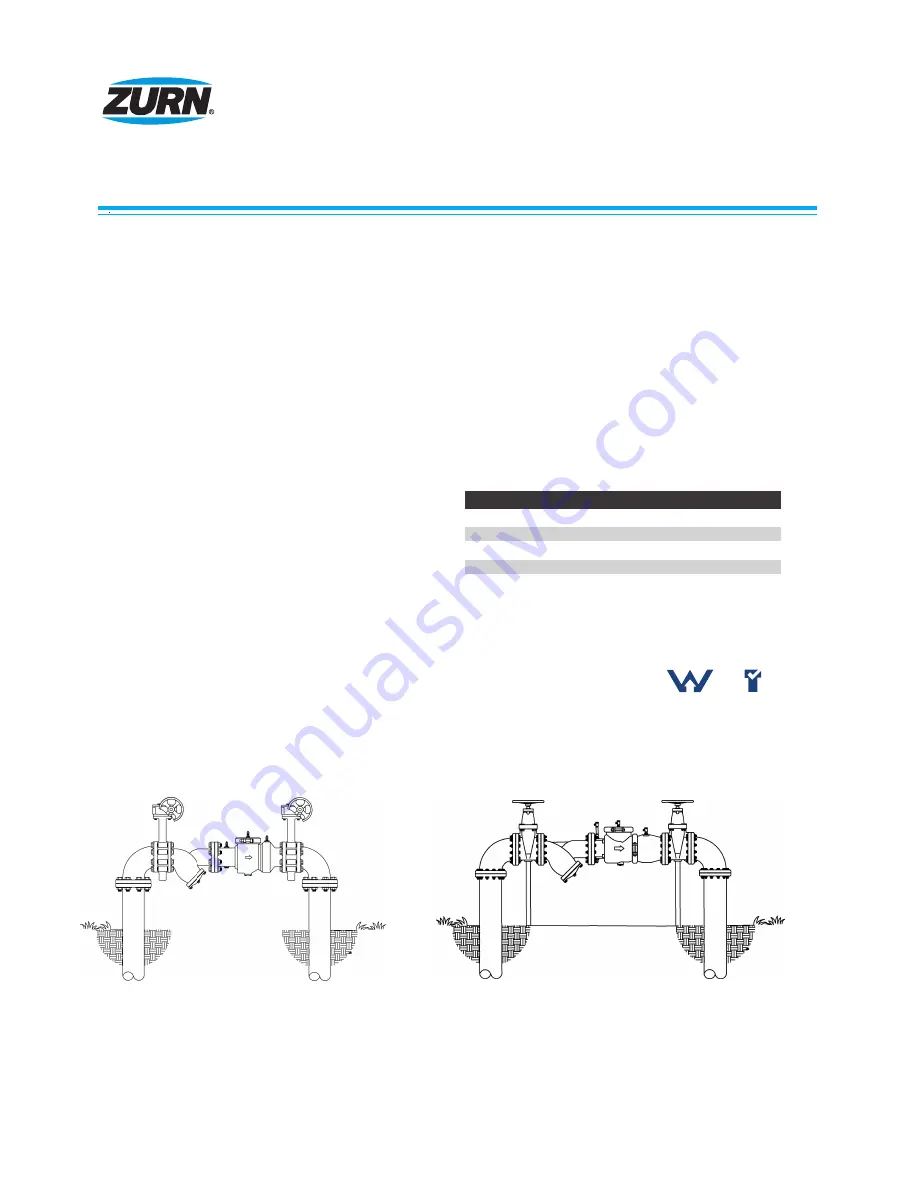
65, 80 & 150mm
200 & 250mm
OUTDOOR INSTALLATION:
The Model 350 Backflow Preventer may be installed outdoors only if the device is protected against
freezing conditions. Exposure to freezing conditions will result in improper function or damage to the device. The installation location
must be kept above 0°C. All the basic installation instructions apply.
DIRECTlON OF FLOW �
WILKINS MODEL 350
DIRECTlON OF FLOW �
WILKINS MODEL 350


