JAN-12
PAGE 9
1. Tank made of polyethylene with a scale divided in 10 l.
2. Tank lid with basket filter.
3. Air deflector with a fan D.560.
4. Pump AR 30 with a safety valve.
5. Remote control with manometer.
6. Sucking filter.
7. Pressure filter.
8. Valve for emptying the tank.
9. Tank mixer (only ZM 200).
10. Frame of the sprayer.
11. Three point connection.
12. Belt tension screw.
13. Belt drive.
14. Nozzle holder with anti drop valves and ceramic nozzles.
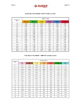
15. Spray rate chart.
16. Warning sticker.
17. Type plate.
18. Grease fitting.
6. WORKING PRINCIPE OF THE SPRAYER
The protection agent flows from the tank through the sucking filter to the pump and from pump
under high pressure through the pressure filter to both spraying sides. With the pressure
regulations valve you can regulate the pressure with the turn the pressure regulation handle to
the right (clockwise) to increase the pressure, or to the left (counterclockwise) to decrease the
pressure.
Before you run the sprayer, turn the regulation handle to the left, so that there is no pressure
on the manometer. When you have working rpm, turn the handle to the right so long, that you
achieve the wanted pressure on the manometer
When the nozzles are closed, all fluid is returning to the tank, when they are operating, a part
of the fluid is for spraying and a part returned in the tank.
Tank mixers must be always on, to secure the homogeneity of the protection agent. When the
level of the fluid sinks under 10 l, you must close them to prevent foaming.
Do not have a pressure above 15 bars. With to high pressure the efficiency of
the spraying sinks. For a higher range of droplets, increase the rpm of the
fan, not the pressure!
WARNING !


