background image

Chapter 6 Service Configuration

Steps

1.

On the

Application

tab, select

QoS

. By default,

Basic

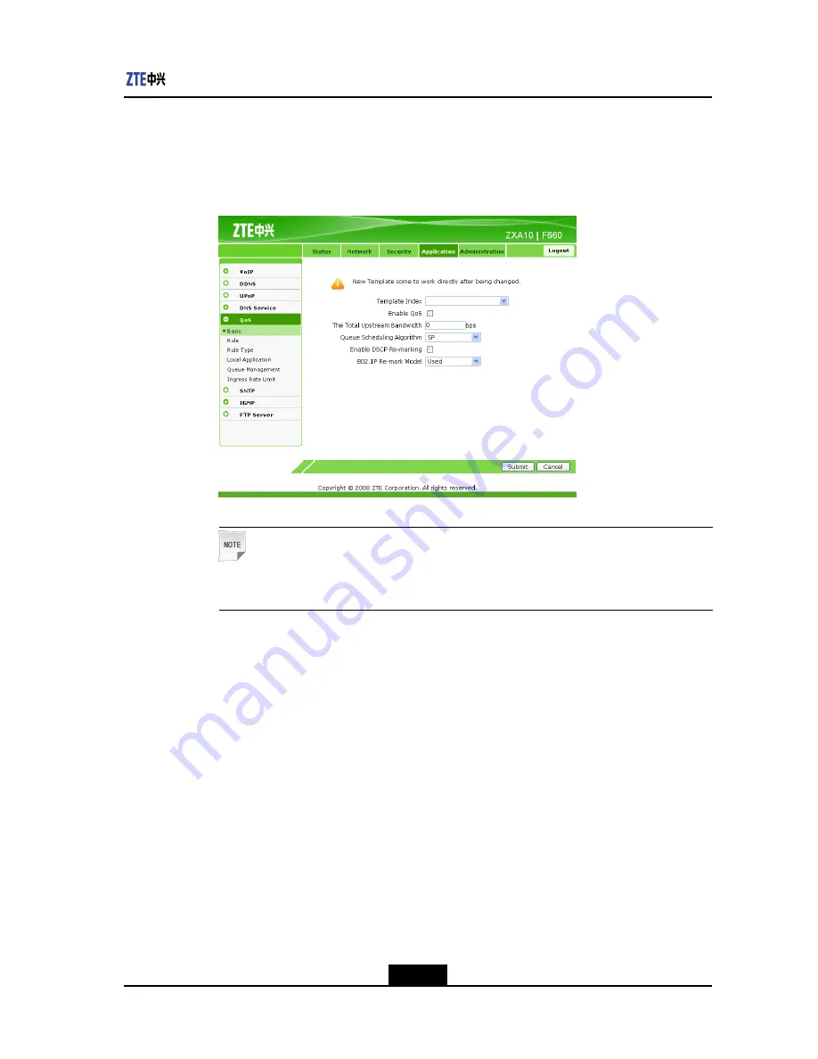
is selected, as shown in

Figure

6-17

.

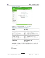
Figure 6-17 Basic QoS Parameters

Note:

The template index is enabled immediately after changed.

2.

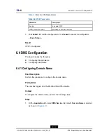
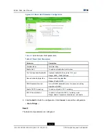
Configure the basic QoS parameters, as shown in

Figure 6-18

.

6-17

SJ-20110718111034-001|2011-07-18 (R1.0)

ZTE Proprietary and Confidential

Summary of Contents for ZXA10 F660

Page 1: ...660 GPON ONT User Manual Version V1 0 ZTE CORPORATION NO 55 Hi tech Road South ShenZhen P R China Postcode 518057 Tel 86 755 26771900 Fax 86 755 26770801 URL http ensupport zte com cn E mail support zte com cn ...

Page 2: ...s for a particular purpose title or non infringement ZTE CORPORATION and its licensors shall not be liable for damages resulting from the use of or reliance on the information contained herein ZTE CORPORATION or its licensors may have current or pending intellectual property rights or applications covering the subject matter of this document Except as expressly provided in any written license betw...

Page 3: ...rmation 3 3 3 3 1 WLAN Interface Information 3 3 3 3 2 Ethernet Interface Information 3 4 3 3 3 VoIP Status Information 3 5 Chapter 4 Network Configuration 4 1 4 1 Configuring WAN Connection 4 1 4 2 WLAN Configuration 4 5 4 2 1 Configuring Basic WLAN Parameters 4 5 4 2 2 Configuring Multi SSID Parameters 4 7 4 2 3 Configuring Security Properties 4 8 4 2 4 Viewing Associated Devices 4 12 4 3 Addres...

Page 4: ...on 6 13 6 4 1 Configuring Domain Name 6 13 6 4 2 Configuring Host Name 6 14 6 5 QoS Configuration 6 16 6 5 1 Configuring Basic QoS Parameters 6 16 6 5 2 Configuring QoS Rule 6 19 6 5 3 Configuring QoS Rule Type 6 20 6 5 4 Configuring QoS Local Application 6 22 6 5 5 Configuring QoS Queue Management 6 23 6 5 6 Configuring QoS Ingress Rate Limit 6 25 6 6 Configuring SNTP Client 6 26 6 7 IGMP Configu...

Page 5: ...ment 7 4 7 3 Device Management 7 5 7 3 1 System Management 7 5 7 3 2 Software Upgrade 7 6 7 3 3 Configuration Management 7 8 7 4 Log Management 7 9 7 5 Ping Diagnosis 7 10 Chapter 8 FAQ 8 1 8 1 FAQ 8 1 Glossary I III ...

Page 6: ...IV ...
Page 7: ... This Manual This manual contains the following chapters Chapter Summary Chapter Summary Chapter 1 Overview Provides an overview of the product including the packing list product features appearance and system requirements and system application environment Chapter 2 Configuration Preparation Describes the procedures for configuring TCP IP and logging in to the device Chapter 3 Device Status Descr...

Page 8: ...s Typeface Meaning Italics References to other Manuals and documents Quotes Links on screens Bold Menus menu options function names input fields radio button names check boxes drop down lists dialog box names window names CAPS Keys on the keyboard and buttons on screens and company name Constant width Text that you type program code files and directory names and function names Optional parameters ...

Page 9: ...uestions comments or suggestions regarding your product contact us by e mail at support zte com cn You can also call our customer support center at 86 755 26771900 and 86 800 9830 9830 Documentation Support ZTE welcomes your comments and suggestions on the quality and usefulness of this document For further questions comments or suggestions on the documentation you can contact us by e mail at doc ...

Page 10: ...alent Chromium Cr VI l PolyBrominated Biphenyls PBB s l PolyBrominated Diphenyl Ethers PBDE s This declaration is issued based on our current level of knowledge Since conditions of use are outside our control ZTE CORPORATION makes no warranties express or implied and assumes no liability in connection with the use of this information IV ...

Page 11: ...e Wi Fi port and two USB 2 0 ports Supports Internet access IPTV VoIP and Wi Fi It can be used as a home gateway ZXA10 F668 Four GE ports two POTS ports one Wi Fi port two USB 2 0 ports and one CATV port Supports Internet access IPTV VoIP Wi Fi and CATV It can be used as a home gateway ZXA10 F600G Four GE ports and two USB 2 0 ports Supports Internet access and IPTV ZXA10 F627 Four GE ports two PO...

Page 12: ...984 5 standards l Ethernet interface 10 100 1000 Mbps GE interfaces RJ 45 in compliance with IEEE 802 3 and IEEE 802 3u standards l POTS interface RJ 11 l WLAN interface complying with the IEEE 802 11n standard with built in antenna Technical Features ZXA10 F660 implements data access and IP voice access l For data access ZXA10 F660 implement L2 data switching and forwarding By working with releva...

Page 13: ...exposure requirement use product that maintain a 20cm distance between the device and human body Note Changes or modifications made to this equipment not expressly approved by ZTE Corporation may void the FCC authorization to operate this equipment Product Specifications ZXA10 F660 specifications are as follows l Rated current 1 3 A l Rated voltage 12 V DC l Operating temperature 5 50 l Operating ...

Page 14: ...The WLAN function is enabled WLAN OFF The device is not powered ON or the wireless interface is disabled Green ON The device is registered on the SS but no data is being transmitted OFF The device is not powered ON or fails to be registered on the SS POTS1 POTS2 Flashing Data is being transmitted Blue ON The device is powered ON normally Power indicator OFF The device is not powered ON Green ON Th...

Page 15: ...rage device or printer that has a USB interface UPS Secondary power monitoring interface POWER Power socket connects to the power adapter 12 V DC WPS WPS access switch WLAN WLAN button to enable or disable WLAN RESET When the device is powered ON press the button for more than 5 seconds to restore the factory default settings Side Panel The side panel has an SC APC single mode fiber interface impl...

Page 16: ... accesses the network should be installed with Windows 98 Me 2000 NT XP Vista 7 or Linux network card driver program and TCP IP protocol and its network settings are correct l A computer in the LAN is installed with a Web browser such as Microsoft Internet Explorer 6 0 or higher Netscape Communicator 4 0 or higher 1 6 System Application Environment ZXA10 F660 is an indoor device of ZTE series opti...

Page 17: ...onment As an indoor device ZXA10 F660 can be put on the desk with the base or hung on the wall without the base Figure 1 5 shows the ZXA10 F660 on a wall Figure 1 5 F66x Wall Mount 1 7 SJ 20110718111034 001 2011 07 18 R1 0 ZTE Proprietary and Confidential ...

Page 18: ...ZXA10 F660 User Manual This page intentionally left blank 1 8 SJ 20110718111034 001 2011 07 18 R1 0 ZTE Proprietary and Confidential ...

Page 19: ...of the computer l Disable any running firewall or security software l Disable the proxy server of the Internet Explorer l Consult the ISP if some data from the ISP is needed 2 2 Configuring TCP IP Short Description Perform this procedure to configure TCP IP of a computer connected to the ZXA10 F660 Context This instance takes Windows XP as an example The default network settings for the ZXA10 F660...

Page 20: ...s dialog box as shown in Figure 2 1 Figure 2 1 Local Area Connection Status 3 Click Properties in the General tab to open the Local Area Connection Properties dialog box 4 Select Internet Protocol TCP IP as shown in Figure 2 2 2 2 SJ 20110718111034 001 2011 07 18 R1 0 ZTE Proprietary and Confidential ...

Page 21: ...IP Properties dialog box Select Use the following IP address and specify the IP address Subnet mask and Default gateway For example you can set the IP address to 192 168 1 7 Subnet mask to 255 255 255 0 and Default gateway to 192 168 1 1 as shown in Figure 2 3 2 3 SJ 20110718111034 001 2011 07 18 R1 0 ZTE Proprietary and Confidential ...

Page 22: ...s LAN port address of the device which means the IP address you type in should be 192 168 1 x x can be any value from 2 to 254 6 Click OK to save your settings Note If you are accessing the WEB page of the device for the first time please configure the device as you are told End of Steps 2 4 SJ 20110718111034 001 2011 07 18 R1 0 ZTE Proprietary and Confidential ...

Page 23: ...gure 2 4 it indicates that the communication between your PC and the device is normal and you are able to access the Internet now Figure 2 4 Successful Ping Message l If the command window displays the messages as shown in Figure 2 5 it indicates that the communication between your PC and the device fails Figure 2 5 Failed Ping Message If the communication between your PC and the device fails ensu...

Page 24: ...ing In to the Device Short Description Perform this procedure to log in to the device Prerequisites The device is properly connected and the computer is correctly configured Context To log in to the device perform the following steps Steps 1 Open the Internet Explorer Enter http 192 168 1 1 default IP address of the device on the address bar and press Enter The login dialog box is displayed as sho...

Page 25: ...r and version information and registration password as shown in Figure 3 1 Figure 3 1 Device Information Table 3 1 lists the parameters for the device information Table 3 1 Device Information Parameters Parameter Description Model Device type Serial Number Device serial number Hardware Version Hardware version number Software Version Software version number Boot Loader Version Boot version number ...

Page 26: ...st information Figure 3 2 WAN Connection Table 3 2 lists the parameters for the network connection information Table 3 2 Parameters for the Network Connection Information Parameter Description omci1 WAN connection type VLAN ID VLAN ID used by the WAN interface to send and receive data NAT Whether to enable the NAT function IP IP address used by ZXA10 F660 DNS DNS used by ZXA10 F660 Default Gateway...

Page 27: ... 1 WLAN Interface Information On the Status tab select User Interface By default WLAN is selected The right pane displays the WLAN switch information packet receiving and sending information and authentication information as shown in Figure 3 3 Click Refresh to view the latest information Figure 3 3 WLAN Interface Information Table 3 3 lists the parameters for the WLAN interface information 3 3 SJ...

Page 28: ...eceived Number of received packets or bytes Packets Sent Bytes Sent Number of sent packets or bytes Error Packets Received Error packets received Error Packets Sent Error packets sent Discarded Receiving Packets Discarded receiving packets Discarded Sending Packets Discarded sending packets 3 3 2 Ethernet Interface Information On the Status tab select User Interface Select Ethernet The right pane ...

Page 29: ... Packets Received Bytes Received Number of received packets or bytes Packets Sent Bytes Sent Number of sent packets or bytes Error Frames Ethernet error frames 3 3 3 VoIP Status Information On the Status tab select User Interface Select VoIP Status The right pane displays the VoIP status information as shown in Figure 3 5 Click Refresh to view the latest information 3 5 SJ 20110718111034 001 2011 ...

Page 30: ...ters for the VoIP status information Table 3 5 Parameters for the VoIP Status Information Parameter Description SIP Account Username Telephone number SIP Register Status Registration status of the voice service 3 6 SJ 20110718111034 001 2011 07 18 R1 0 ZTE Proprietary and Confidential ...

Page 31: ...ion Perform this procedure to configure the WAN connection Prerequisites The user has logged in to the Web interface of the device Context To configure the WAN connection perform the following steps Steps 1 On the Web interface of the device click the Network tab By default WAN Connection is selected as shown in Figure 4 1 Figure 4 1 WAN Connection 4 1 SJ 20110718111034 001 2011 07 18 R1 0 ZTE Pro...

Page 32: ...d by the system Enable NAT Whether to enable the NAT function Service List Service modes supported by the system l TR069 service mode Remote maintenance and management mode l Internet service mode Broadband and IPTV service mode l VoIP service mode Voice service mode VLAN ID VLAN ID Username User name used by the device authentication on interworking Password Password used by the device authentica...

Page 33: ... 4 2 lists the parameters for the static mode configuration Table 4 2 Static Mode Configuration Parameter Description Type Connection mode Connection Name Static connection name automatically generated by the system Enable NAT Whether to enable the NAT function Service List Service modes supported by the system l TR069 service mode Remote maintenance and management mode l Internet service mode Bro...

Page 34: ...e as shown in Figure 4 4 Figure 4 4 DHCP Mode Configuration Table 4 3 lists the parameters for the DHCP mode configuration Table 4 3 DHCP Mode Configuration Parameter Description Type Connection mode Connection Name DHCP connection name automatically generated by the system Enable NAT Whether to enable the NAT function Service List Service modes supported by the system l TR069 service mode Remote ...

Page 35: ...ring Security Properties l Viewing Associated Devices 4 2 1 Configuring Basic WLAN Parameters Short Description Perform this procedure to configure the basic WLAN parameters Prerequisites The user has logged in to the Web interface of the device Context To configure the basic WLAN parameters perform the following steps Steps 1 On the Network tab select WLAN on the left pane By default the Basic su...

Page 36: ...y code Beacon Interval Beacon interval Tx Rate Data transmission rate A low data transmission rate can enlarge the wireless communication area Transmitting Power Transmission power QoS Type QoS priority type RTS Threshold RTS threshold DTIM Interval DTIM interval Fragment Threshold Fragment threshold If a packet size exceeds this threshold the packet is divided into several fragments for transmiss...

Page 37: ... SSID parameters perform the following steps Steps 1 On the Network tab click WLAN on the left pane Select Multi SSID Settings as shown in Figure 4 6 Figure 4 6 Multi SSID Settings 2 Configure the multi SSID parameters as shown in Table 4 5 Table 4 5 Multi SSID Parameters Parameter Description Choose SSID Choose the SSID that needs to be configured Hide SSID Disable or enable SSID broadcast Enable...

Page 38: ...f Steps Result The multi SSID parameters are configured 4 2 3 Configuring Security Properties Short Description Perform this procedure to configure the security properties Prerequisites The user has logged in to the Web interface of the device Context To configure the security properties perform the following steps Steps 1 On the Network tab select WLAN and then select Security as shown in Figure ...

Page 39: ...ion Type Current SSID authentication mode WEP Encryption To enable or disable WEP encryption WEP Encryption Level WEP encryption length l The 128 bit encryption can be a 13 bit ASCII codes or a 26 bit hexadecimal number l The 64 bit encryption can be a 5 bit ASCII code or a 10 bit hexadecimal number Generally the 64 bit encryption can meet the user requirements To enhance security use the 128 bit ...

Page 40: ...hentication mode Table 4 7 Parameters for Shared Key Authentication Mode Parameter Description Choose SSID Current SSID Authentication Type Current SSID authentication mode WEP Encryption To enable or disable WEP encryption WEP Encryption Level WEP encryption length l The 128 bit encryption can be a 13 bit ASCII codes or a 26 bit hexadecimal number l The 64 bit encryption can be a 5 bit ASCII code...

Page 41: ...on Type select WPA PSK The WPA PSK configuration information is displayed as shown in Figure 4 10 Figure 4 10 WPA PSK Configuration Table 4 8 lists the parameters for the WPA PSK authentication mode Table 4 8 Parameters for WPA PSK Authentication Mode Parameter Description Choose SSID Current SSID Authentication Type Current SSID authentication mode WPA Passphrase WPA pre shared key Range 8 63 cha...

Page 42: ...erties are configured 4 2 4 Viewing Associated Devices Short Description Perform this procedure to view the associated devices Prerequisites The user has logged in to the Web interface of the device Context To view the associated devices perform the following steps Steps 1 On the Network tab select WLAN and then select Associated Device as shown in Figure 4 11 Figure 4 11 Associated Device 4 12 SJ...

Page 43: ...guring DHCP Binding l Configuring Specific Address Range 4 3 1 Configuring DHCP Server Short Description Perform this procedure to configure the DHCP server Prerequisites The user has logged in to the Web interface of the device Context To configure the DHCP server perform the following steps Steps 1 On the Network tab select Address Management By default DHCP Server is selected as shown in Figure...

Page 44: ... IP address allocated by the DHCP server DHCP End IP Address Ending IP address allocated by the DHCP server DNS Server1 IP Address IP address of the DNS server DNS Server2 IP Address IP address of the DNS server DNS Server3 IP Address IP address of the DNS server Default Gateway IP address of the default gateway Lease Time Lease time of the IP address by the DHCP server 3 Click Submit to finish th...

Page 45: ...tween the MAC address and IP address Create a DHCP binding table to map the client MAC address to the IP address The DHCP server allocates IP addresses according to the binding relations and the binding relations do not expire For example if the MAC address is set to 00 0a e2 c6 48 ba and the IP address is set to 192 168 1 113 it indicates that the DHCP server allocates the IP address 192 168 1 11...

Page 46: ...o configure the specific address range Prerequisites The user has logged in to the Web interface of the device Context To configure the special address range perform the following steps Steps 1 On the Network tab select Address Management and then select Specific Address Range as shown in Figure 4 14 Figure 4 14 Specific Address Range 2 Click Modify to modify the parameters as shown in Figure 4 15...

Page 47: ...l Configuring Default Gateway l Configuring Static Routing 4 4 1 Configuring Default Gateway Short Description Perform this procedure to configure the default gateway Prerequisites The user has logged in to the Web interface of the device Context To configure the default gateway perform the following steps Steps 1 On the Network tab select Routing Management By default Default Gateway is selected ...

Page 48: ...f Steps Result The default gateway is configured 4 4 2 Configuring Static Routing Short Description Perform this procedure to configure the static routing Prerequisites The user has logged in to the Web interface of the device Context To configure the static routing perform the following steps Steps 1 On the Network tab select Routing Management and then select Static Routing as shown in Figure 4 ...

Page 49: ...ess Subnet Mask Subnet mask Default Gateway Gateway 2 From the WAN Connection drop down list select the network side interface 3 Configure Network Address Subnet Mask and Default Gateway as shown in Figure 4 18 Figure 4 18 Static Routing Configuration 4 Click Add to finish the configuration as shown in Figure 4 19 Click Modify to modify the configuration Click Delete to delete the configuration 4 ...

Page 50: ...ZXA10 F660 User Manual Figure 4 19 Static Routing Configuration Completed End of Steps Result The static routing is configured 4 20 SJ 20110718111034 001 2011 07 18 R1 0 ZTE Proprietary and Confidential ...

Page 51: ...is procedure to configure the firewall Prerequisites The user has logged in to the Web interface of the device Context To configure the firewall perform the following steps Steps 1 On the Web interface click the Security tab By default Firewall is selected as shown in Figure 5 1 Figure 5 1 Firewall Configuration 2 Set the firewall parameters as listed in Table 5 1 5 1 SJ 20110718111034 001 2011 07...

Page 52: ... 3 Click Submit to finish the configuration Click Cancel to cancel the configuration End of Steps Result The firewall is configured 5 2 Configuring IP Filter Short Description Perform this procedure to configure IP filter Prerequisites The user has logged in to the Web interface of the device Context To configure IP filter perform the following steps Steps 1 On the Security tab select IP Filter as...

Page 53: ...ress Ending source IP address Start Destination IP Address Starting destination IP address End Destination IP Address Ending destination IP address Start Source Port Starting source port number End Source Port Ending source port number Start Destination Port Starting destination port number End Destination Port Ending destination port number Ingress Ingress interface Egress Egress interface Mode D...

Page 54: ... shown in Figure 5 3 Figure 5 3 IP Filter Configuration 3 Click Add to finish the configuration as shown in Figure 5 4 Click Modify to modify the configuration Click Delete to delete the configuration 5 4 SJ 20110718111034 001 2011 07 18 R1 0 ZTE Proprietary and Confidential ...

Page 55: ... Short Description Perform this procedure to configure the URL filter Prerequisites The user has logged in to the Web interface of the device Context To configure the URL filter perform the following steps Steps 1 On the Security tab select URL Filter as shown in Figure 5 5 5 5 SJ 20110718111034 001 2011 07 18 R1 0 ZTE Proprietary and Confidential ...

Page 56: ... To enable the URL filter function Mode Mode including discard and permit URL Address URL address 2 On the URL Filter tab set the filter parameters as shown in Figure 5 6 Figure 5 6 URL Filter Configuration 3 Click Add to finish the configuration as shown in Figure 5 7 Click Delete to delete the configuration 5 6 SJ 20110718111034 001 2011 07 18 R1 0 ZTE Proprietary and Confidential ...

Page 57: ...ost Short Description Perform this procedure to configure the DMZ host Prerequisites The user has logged in to the Web interface of the device Context To configure the DMZ host perform the following steps Steps 1 On the Security tab select DMZ Host as shown in Figure 5 8 5 7 SJ 20110718111034 001 2011 07 18 R1 0 ZTE Proprietary and Confidential ...

Page 58: ...er Description Enable To enable the DMZ host WAN Connection WAN side connection interface DMZ Host IP Address IP address of the DMZ host Note After the DMZ full port mapping function is enabled all the ports are enabled by default The LAN side host provides services through DNAT 3 Click Submit to finish the configuration Click Cancel to cancel the configuration End of Steps 5 8 SJ 20110718111034 0...

Page 59: ...quisites The user has logged in to the Web interface of the device Context To configure port forwarding perform the following steps Steps 1 On the Security tab select Port Forwarding as shown in Figure 5 10 Figure 5 10 Port Forwarding 2 Configure the port forwarding parameters as shown in Figure 5 11 5 9 SJ 20110718111034 001 2011 07 18 R1 0 ZTE Proprietary and Confidential ...

Page 60: ... of the WAN side host WAN Connection WAN connection WAN Start Port Starting port number of the WAN side host WAN End Port Ending port number of the WAN side host LAN Host IP Address IP address of the LAN side host LAN Host Port Port number of the LAN side host Note If a redirection policy of port access with the source address of the WAN side IP address and the destination address of the LAN side ...

Page 61: ...hown in Figure 5 12 Click Modify to modify the configuration Click Delete to delete the configuration Figure 5 12 Port Forwarding Configuration Completed End of Steps Result Port forwarding is configured 5 11 SJ 20110718111034 001 2011 07 18 R1 0 ZTE Proprietary and Confidential ...

Page 62: ...ZXA10 F660 User Manual This page intentionally left blank 5 12 SJ 20110718111034 001 2011 07 18 R1 0 ZTE Proprietary and Confidential ...

Page 63: ...l Configuring SIP Accounts l Configuring VoIP Advanced Parameters l Configuring VoIP Media Parameters l Configuring Fax 6 1 1 Configuring VoIP WAN Connection Short Description Perform this procedure to configure the VoIP WAN connection Prerequisites The user has logged in to the Web interface of the device Context To configure the VoIP WAN connection perform the following steps Steps 1 On the Web ...

Page 64: ... VoIP WAN connection is configured 6 1 2 Configuring SIP Short Description Perform this procedure to configure SIP Prerequisites The user has logged in to the Web interface of the device Context To configure SIP perform the following steps Steps 1 On the Application tab select VoIP and then select SIP Protocol as shown in Figure 6 2 6 2 SJ 20110718111034 001 2011 07 18 R1 0 ZTE Proprietary and Con...

Page 65: ...he primary outbound proxy server Primary Proxy Port Port number of the primary proxy server Secondary Proxy Server IP address of the secondary proxy server Secondary Outbound Proxy Server IP address of the secondary outbound proxy server Secondary Proxy Port Port number of the secondary proxy server Register Expires Registration expiration time Unit second 3 Click Submit to finish the configuratio...

Page 66: ...o the Web interface of the device Context To configure SIP accounts perform the following steps Steps 1 On the Application tab select VoIP and then select SIP Accounts as shown in Figure 6 3 Figure 6 3 SIP Accounts 2 Click Modify to modify the account parameters as shown in Figure 6 4 6 4 SJ 20110718111034 001 2011 07 18 R1 0 ZTE Proprietary and Confidential ...

Page 67: ...word Password of the SIP authentication user URI User registration identification that is the user SIP call number 3 Click Modify End of Steps Result The SIP accounts are configured 6 1 4 Configuring VoIP Advanced Parameters Short Description Perform this procedure to configure the VoIP advanced parameters Prerequisites The user has logged in to the Web interface of the device 6 5 SJ 2011071811103...

Page 68: ...meters Parameter Description Echo Cancellation To enable or disable echo cancellation VAD CNG To enable or disable VAD and CNG DTMF DTMF mode including RFC2833 RFC2198 and DTMF in Voice Jitter Buffer Jitter buffer including fixed and adaptive Min Value Minimum jitter buffer value Unit ms Max Value Maximum jitter buffer value Unit ms 3 Click Submit to finish the configuration Click Cancel to cancel...

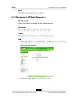
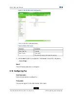
Page 69: ...ameters Prerequisites The user has logged in to the Web interface of the device Context To configure VoIP media parameters perform the following steps Steps 1 On the Application tab select VoIP and then select Media as shown in Figure 6 6 Figure 6 6 Media Parameters 2 Configure the media parameters as shown in Figure 6 7 6 7 SJ 20110718111034 001 2011 07 18 R1 0 ZTE Proprietary and Confidential ...

Page 70: ...ler the value is the higher the priority is 3 Click Submit to finish the configuration Click Cancel to cancel the configuration End of Steps Result The VoIP media parameters are configured 6 1 6 Configuring Fax Short Description Perform this procedure to configure fax Prerequisites The user has logged in to the Web interface of the device 6 8 SJ 20110718111034 001 2011 07 18 R1 0 ZTE Proprietary a...

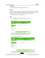
Page 71: ...then select Fax as shown in Figure 6 8 Figure 6 8 Fax Configuration 2 Select Enable T38 Note To disable T38 fax mode clear the check box 3 Click Submit to finish the configuration Click Cancel to cancel the configuration End of Steps Result Fax is configured 6 9 SJ 20110718111034 001 2011 07 18 R1 0 ZTE Proprietary and Confidential ...

Page 72: ...ample when the host obtains an IP address through xDSL dial up or DHCP server dynamic allocation and the host provides the domain name service by using DDNS the effect on the domain name access when the IP address changes is eliminated To configure DDNS perform the following steps Steps 1 On the Application tab select DDNS as shown in Figure 6 9 Figure 6 9 DDNS 2 Configure the DDNS parameters as s...

Page 73: ...t is http ns eagleeyes com cn cgi bin gdipupdt cgi Username DDNS server user name Password DDNS server password Domain Domain name corresponding to the user valid only when the GNUDIP protocol is used WAN Connection WAN side connection interface 3 Click Submit to finish the configuration Click Cancel to cancel the configuration End of Steps Result DDNS is configured 6 3 Configuring UPnP Short Desc...

Page 74: ...e can be dynamically added to a network to obtain the IP address announce the function and know the functions of other devices To configure UPnP perform the following steps Steps 1 On the Application tab select UPnP as shown in Figure 6 11 Figure 6 11 UPnP 2 Configure the UPnP parameters as shown in Figure 6 12 Figure 6 12 UPnP Configuration 6 12 SJ 20110718111034 001 2011 07 18 R1 0 ZTE Proprieta...

Page 75: ... Configuration This topic includes the following l Configuring Domain Name l Configuring Host Name 6 4 1 Configuring Domain Name Short Description Perform this procedure to configure the domain name Prerequisites The user has logged in to the Web interface of the device Context To configure the domain name perform the following steps Steps 1 On the Application tab select DNS Service By default Dom...

Page 76: ... 4 2 Configuring Host Name Short Description Perform this procedure to configure the host name Prerequisites The user has logged in to the Web interface of the device Context To configure the host name perform the following steps Steps 1 On the Application tab select DNS Service and then select Hosts as shown in Figure 6 14 6 14 SJ 20110718111034 001 2011 07 18 R1 0 ZTE Proprietary and Confidentia...

Page 77: ...ss as shown in Figure 6 15 Figure 6 15 Host Name Configuration 3 Click Add to finish the configuration as shown in Figure 6 16 Click Modify to modify the configuration Click Delete to delete the configuration 6 15 SJ 20110718111034 001 2011 07 18 R1 0 ZTE Proprietary and Confidential ...

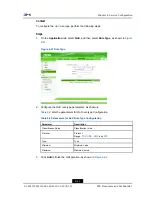
Page 78: ...e Type l Configuring QoS Local Application l Configuring QoS Queue Management l Configuring QoS Ingress Rate Limit 6 5 1 Configuring Basic QoS Parameters Short Description Perform this procedure to configure the basic QoS parameters Prerequisites The user has logged in to the Web interface of the device Context To configure the basic QoS parameters perform the following steps 6 16 SJ 2011071811103...

Page 79: ...efault Basic is selected as shown in Figure 6 17 Figure 6 17 Basic QoS Parameters Note The template index is enabled immediately after changed 2 Configure the basic QoS parameters as shown in Figure 6 18 6 17 SJ 20110718111034 001 2011 07 18 R1 0 ZTE Proprietary and Confidential ...

Page 80: ...duling Algorithm Queue scheduling algorithm Range SP and DWRR DWRR bandwidth locked To lock DWRR bandwidth when the queue scheduling algorithm is DWRR Enable DSCP Re marking To enable or disable DSCP remarking 802 1P Re mark Model To enable or disable the 802 1p remarking mode Range disable transparent transmission and enable 3 Click Submit to finish the configuration Click Cancel to cancel the co...

Page 81: ...s logged in to the Web interface of the device Context To configure the QoS rule perform the following steps Steps 1 On the Application tab select QoS and then select Rule as shown in Figure 6 19 Figure 6 19 QoS Rule 2 Configure the QoS rule parameters as shown in Figure 6 20 6 19 SJ 20110718111034 001 2011 07 18 R1 0 ZTE Proprietary and Confidential ...

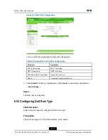
Page 82: ...mmitted Access Rate Ingress rate limit rule Queue Congestion management queue 3 Click Submit to finish the configuration Click Cancel to cancel the configuration End of Steps Result The QoS rule is configured 6 5 3 Configuring QoS Rule Type Short Description Perform this procedure to configure the QoS rule type Prerequisites The user has logged in to the Web interface of the device 6 20 SJ 2011071...

Page 83: ...e parameters as shown in Table 6 9 lists the parameters for QoS rule type Configuration Table 6 9 Parameters for QoS Rule Type Configuration Parameter Description Classification Rules Classification rules Protocol Protocol Range TCP UDP ICMP and RTP Type Type Minimum Minimum value Maximum Maximum value 3 Click Add to finish the configuration as shown in Figure 6 22 6 21 SJ 20110718111034 001 2011 ...

Page 84: ...QoS Local Application Short Description Perform this procedure to configure the QoS local application Prerequisites The user has logged in to the Web interface of the device Context To configure the QoS local application perform the following steps Steps 1 On the Application tab select QoS and then select Local Application as shown in Figure 6 23 6 22 SJ 20110718111034 001 2011 07 18 R1 0 ZTE Prop...

Page 85: ...ncel to cancel the configuration End of Steps Result The QoS local application is configured 6 5 5 Configuring QoS Queue Management Short Description Perform this procedure to configure QoS queue management Prerequisites The user has logged in to the Web interface of the device Context To configure QoS queue management perform the following steps 6 23 SJ 20110718111034 001 2011 07 18 R1 0 ZTE Prop...

Page 86: ...to enable or disable the queue management function 4 Click Modify to finish the configuration Note 1 indicates enabled and 0 indicates disabled When the congestion management algorithm is DWRR the queue weight needs to be configured Weight refers to the ratio of the data flow passing through the queues to the total data flow End of Steps Result QoS queue management is configured 6 24 SJ 2011071811...

Page 87: ... the Web interface of the device Context To configure the QoS ingress rate limit perform the following steps Steps 1 On the Application tab select QoS and then select Ingress Rate Limit as shown in Figure 6 25 Figure 6 25 Ingress Rate Limit 2 Configure the parameters for QoS ingress rate limit as shown in Figure 6 26 6 25 SJ 20110718111034 001 2011 07 18 R1 0 ZTE Proprietary and Confidential ...

Page 88: ...e ingress rate limit function Rate Limit rate 8000 bps 104857600 bps 3 Click Add to finish the configuration Click Modify to modify the configuration Click Delete to delete the configuration End of Steps Result The QoS ingress rate limit is configured 6 6 Configuring SNTP Client Short Description Perform this procedure to configure the SNTP client Prerequisites The user has logged in to the Web in...

Page 89: ... 27 SNTP 2 Configure the SNTP parameters as shown in Figure 6 27 Figure 6 28 SNTP Configuration Table 6 11 lists the SNTP parameters Table 6 11 SNTP Parameters Parameter Description Time Zone Time zone where the subscriber is located Primary NTP Server Address IP address of the primary NTP server 6 27 SJ 20110718111034 001 2011 07 18 R1 0 ZTE Proprietary and Confidential ...

Page 90: ...l Configuring Basic IGMP Parameters l Configuring Multicast VLAN l Configuring Multicast MAC Limit l Configuring MVLAN Tag Strip 6 7 1 Configuring Basic IGMP Parameters Short Description Perform this procedure to configure the basic IGMP parameters Prerequisites The user has logged in to the Web interface of the device Context To configure the basic IGMP parameters perform the following steps Step...

Page 91: ...rom the IGMP Mode drop down list select IGMP Snooping as shown in Figure 6 30 Figure 6 30 IGMP Snooping Configuration Table 6 12 lists the parameters for IGMP snooping configuration Table 6 12 Parameters for IGMP Snooping Configuration Parameter Description IGMP Mode IGMP mode Multicast MAC Aging Time Aging time of the multicast address 6 29 SJ 20110718111034 001 2011 07 18 R1 0 ZTE Proprietary an...

Page 92: ...arameters for IGMP Proxy Configuration Parameter Description IGMP Mode IGMP mode Multicast MAC Aging Time Aging time of the multicast address Report Time Periodical report time of multicast messages Note ZXA10 F660 periodically reports the IGMP member report messages to the upper layer multicast router according to the Report Time 3 Click Submit to finish the configuration Click Cancel to cancel t...

Page 93: ...ites The user has logged in to the Web interface of the device Context To configure the multicast VLAN perform the following steps Steps 1 On the Application tab select IGMP and then select Multicast VLAN as shown in Figure 6 32 Figure 6 32 Multicast VLAN 2 Configure the multicast VLAN parameters as shown in Figure 6 33 6 31 SJ 20110718111034 001 2011 07 18 R1 0 ZTE Proprietary and Confidential ...

Page 94: ...ticast VLAN translation Multicast VLAN To create a multicast VLAN New VLAN Multicast VLAN ID Interface Name LAN interface to be added to the multicast VLAN 3 Click Submit to finish the configuration Click Cancel to cancel the configuration End of Steps Result The multicast VLAN is configured 6 7 3 Configuring Multicast MAC Limit Short Description Perform this procedure to configure multicast MAC l...

Page 95: ...wing steps Steps 1 On the Application tab select IGMP and then select Multicast MAC Limit as shown in Figure 6 34 Figure 6 34 Multicast MAC Limit 2 Click the Modify icon to configure the multicast MAC limit as shown in Figure 6 35 Figure 6 35 Multicast MAC Limit Configuration Table 6 15 lists the parameters for the multicast MAC limit configuration 6 33 SJ 20110718111034 001 2011 07 18 R1 0 ZTE Pr...

Page 96: ... Description Perform this procedure to configure MVLAN tag strip Prerequisites The user has logged in to the Web interface of the device Context The MVLAN tag strip function can be configured only when the IGMP mode is IGMP Snooping IGMP Proxy does not support this function To configure MVLAN tag strip perform the following steps Steps 1 On the Application tab select IGMP and then select Tag Strip...

Page 97: ...Strip Configuration Table 6 16 lists the parameters for MVLAN tag strip configuration Table 6 16 Parameters for MVLAN Tag Strip Configuration Parameter Description Enable Tag Stripe To enable the MVLAN tag strip function 3 Click Modify End of Steps Result MVLAN tag strip is configured 6 35 SJ 20110718111034 001 2011 07 18 R1 0 ZTE Proprietary and Confidential ...

Page 98: ... Web interface of the device Context To configure FTP application perform the following steps Steps 1 On the Application tab select FTP Application as shown in Figure 6 38 Figure 6 38 FTP Server 2 Configure the FTP server parameters as shown in Figure 6 39 Figure 6 39 FTP Server Configuration 6 36 SJ 20110718111034 001 2011 07 18 R1 0 ZTE Proprietary and Confidential ...

Page 99: ...iption Enable FTP Server To enable the FTP server FTP Username FTP login user name FTP Password FTP login password 3 Click Submit to finish the configuration Click Cancel to cancel the configuration End of Steps Result FTP application is configured 6 37 SJ 20110718111034 001 2011 07 18 R1 0 ZTE Proprietary and Confidential ...

Page 100: ...ZXA10 F660 User Manual This page intentionally left blank 6 38 SJ 20110718111034 001 2011 07 18 R1 0 ZTE Proprietary and Confidential ...

Page 101: ...RO69 Certificate 7 1 1 Configuring Basic TR069 Parameters Short Description Perform this procedure to configure the basic TR069 parameters Prerequisites The user has logged in to the Web interface of the device Context To configure the basic TR069 parameters perform the following steps Steps 1 On the Administration tab select TR 069 By default Basic is selected as shown in Figure 7 1 7 1 SJ 201107...

Page 102: ...1 lists the basic TR069 parameters Table 7 1 Basic TR069 Parameters Parameter Description WAN Connection WAN side connection interface ACS URL Network server URL Username User name Password Password Connection Request URL Connection request URL Connection Request Username Connection request user name 7 2 SJ 20110718111034 001 2011 07 18 R1 0 ZTE Proprietary and Confidential ...

Page 103: ...Result The basic TR069 parameters are configured 7 1 2 Importing TRO69 Certificate Short Description Perform this procedure to import the TR069 certificate Prerequisites The user has logged in to the Web interface of the device Context To import the TR069 certificate perform the following steps Steps 1 On the Administration tab select TR 069 and then select Certificate as shown in Figure 7 3 Figur...

Page 104: ...rs Prerequisites The user has logged in to the Web interface of the device Context To manage users perform the following steps Steps 1 On the Administration tab select User Management as shown in Figure 7 4 Figure 7 4 User Management 2 Configure the user management parameters Note User Right includes Administrator and User 7 4 SJ 20110718111034 001 2011 07 18 R1 0 ZTE Proprietary and Confidential ...

Page 105: ...onfiguration Management 7 3 1 System Management Short Description Perform this procedure to manage the system Prerequisites The user has logged in to the Web interface of the device Context To manage the system perform the following steps Steps 1 On the Administration tab select System Management as shown in Figure 7 5 Figure 7 5 System Management 2 Click Reboot to reboot the device 7 5 SJ 2011071...

Page 106: ...e is upgraded by the ZTE CORPORATION engineers If the user wants to upgrade the software contact the local office of ZTE CORPORATION to obtain the latest software version To upgrade the software perform the following steps Steps 1 On the Administration tab select System Management and then select Software Upgrade as shown in Figure 7 6 Figure 7 6 Software Upgrade 2 Click Browse to select the softw...

Page 107: ...ed Note During the upgrade process the device cannot be powered off otherwise it may be damaged During the upgrade process the system prompts a message After the upgrade is complete the system returns to the login interface End of Steps Result The software is upgraded 7 7 SJ 20110718111034 001 2011 07 18 R1 0 ZTE Proprietary and Confidential ...

Page 108: ... steps Steps 1 On the Administration tab select System Management and then select Configuration Management as shown in Figure 7 9 Figure 7 9 Configuration Management 2 Click Backup Configuration to back up the existing configuration file 3 Click Browse to select the backed up configuration file 4 Click Restore Configuration to restore the backed up configuration file as shown in Figure 7 10 7 8 SJ...

Page 109: ...gement Short Description Perform this procedure to manage logs Prerequisites The user has logged in to the Web interface of the device Context To manage logs perform the following steps Steps 1 On the Administration tab select Log Management as shown in Figure 7 11 7 9 SJ 20110718111034 001 2011 07 18 R1 0 ZTE Proprietary and Confidential ...

Page 110: ...el is configured only the logs above the specified level are saved 3 Click Refresh to display the latest 20 logs 4 Click Clear Log to clear the current log records 5 Click Submit to finish the configuration Click Cancel to cancel the configuration End of Steps Result Log management is complete 7 5 Ping Diagnosis Short Description Perform this procedure to diagnose ping connection Prerequisites The...

Page 111: ...2 Figure 7 12 Ping Diagnosis 2 In Input IP Address or host name enter the host IP address or host name 3 Click Submit to diagnose the connection as shown in Figure 7 13 Click Cancel to cancel the configuration Figure 7 13 Ping Diagnosis Result End of Steps Result Ping diagnosis is complete 7 11 SJ 20110718111034 001 2011 07 18 R1 0 ZTE Proprietary and Confidential ...

Page 112: ...ZXA10 F660 User Manual This page intentionally left blank 7 12 SJ 20110718111034 001 2011 07 18 R1 0 ZTE Proprietary and Confidential ...

Page 113: ...How Can I Restore the Device to the Factory Default Settings Press the RST reset button for more than 10 seconds to reboot the device Then the device is restored to the factory default settings Why Is the PON Link Indicator Always OFF If the PON link indicator is always OFF it indicates that the PON link is not successfully set up Make sure that the fiber is correctly connected with the PON port a...

Page 114: ...ZXA10 F660 User Manual This page intentionally left blank 8 2 SJ 20110718111034 001 2011 07 18 R1 0 ZTE Proprietary and Confidential ...

Page 115: ...militarized Zone DNAT Destination Network Address Translation DNS Domain Name Server DSCP Differentiated Services Code Point DSL Digital Subscriber Line DTMF Dual ToneMulti Frequency DWRR Deficit Weighted Round Robin FTP File Transfer Protocol FTTH Fiber to the Home GE Gigabit Ethernet GPON Gigabit Passive Optical Network HTTP Hypertext Transfer Protocol I ...

Page 116: ...ernet Service Provider ITU International Telecommunications Union LAN Local Area Network MAC Medium Access Control NAT Network Address Translation NTP Network Time Protocol OLT Optical Line Terminal OMCI ONT Management Control Interface ONT Optical Network Terminal ONU Optical Network Unit PON Passive Optical Network POTS Plain Old Telephone Service PPPoE Point to Point Protocol over Ethernet QoS ...

Page 117: ... Transfer Control Protocol TCP IP Transfer Control Protocol Internet Protocol UDP User Datagram Protocol URL UniformResource Locator VAD Voice Activity Detectors VLAN Virtual Local Area Network VoIP Voice over Internet Protocol WAN Wide Area Network WEP Wired Equivalent Privacy WLAN Wireless Local Area Network WPA Wi Fi Protected Access Wi Fi Wireless Fidelity III ...

Reviews: