background image


NVIDIA ION PCIEx16 series Motherboard

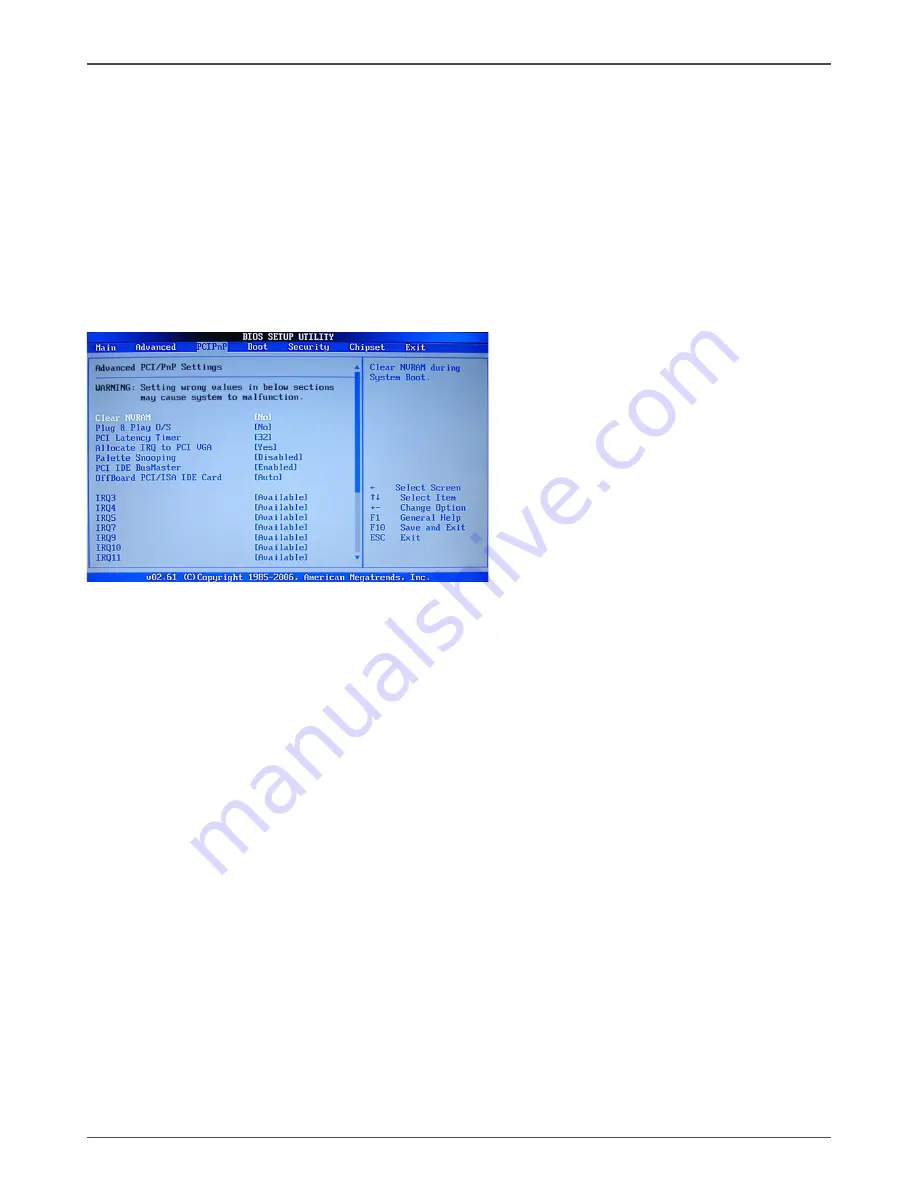
PCI/PnP Menu

The  PCI  PnP  menu  items  allow  you  to  change  the  advanced  settings  for  PCI/PnP 

devices. The menu includes setting IRQ and DMA channel resources for either PCI/

PnP or legacy ISA devices , and setting the memory size block for legacy ISA devices. 

Press <enter> To display the configuration options:

Clear NVRAM

The items allow you to select whether clear NVRAM during system boot.

Plug and Play O/S


When  set  to  [No],  BIOS  configure  all  the  devices  in  the  system.  When  set  to 

[YES] and if you install a Plug and Play operating system, the operating system 

configures the Plug and Play devices not required for boot.

PCI Latency Timer


Allows you to select the value in units of PCI clocks for PCI device latency timer 

register.

Allocate IRQ to PCI VGA


When set to [YES], BIOS assigns an IRQ to PCI VGA card if the requests for an 

IRQ. When set to [No], BIOS does not assign an IRQ to the PCI VGA card even 

if requested .

Palette Snooping

When set to [enable], the pallete snooping feature informs the PCI devices that 

an ISA graphics device is installed in the system so that the latter can function 

correctly.

PCI IDE BusMaster

When  set  to  [enable],  BIOS  use  PCI  busmastering  for  reading  /writing  to  IDE 

drives.


OffBoard PCI/ISA IDE Card

Use this option to set the PCI slot number for some PCI IDE Cards holding.


IRQ-xx assigned to


When  set  to  [PCI  Device],  the  specific  IRQ  is  free  for  use  of  PCI/PnP  devices. 

When set to [Reserved], the IRQ is reserved for legacy ISA devices.

BIOS EHCI Hand-Off

Allows  you  to  enable  support  for  operating  systems  without  an  EHCI  hand-off 

feature.

Summary of Contents for IONITX-F series

Page 1: ......

Page 2: ...ONNECT THE EQUIPMENT INTO AN OUTLET ON A CIRCUIT DIFFERENT FROM THAT OF THE RECEIVER CONSULT THE DEALER OR AN EXPERIENCED AUDIO TELEVISION TECHNICIAN NOTE Connecting this device to peripheral devices...

Page 3: ...r COM 14 SPK Header 14 USB Headers 14 SPDIF out Header 15 Front Panel Header 15 Connecting Serial ATA Cables 16 Fan Connections 16 Expansion Slots 17 Mini PCIE Slot 17 PCI Express x16 slots 17 Jumper...

Page 4: ...37 Frequently Used Equalizer Setting 37 Karaoke Mode 37 Mixer 38 Playback control 38 Recording control 39 Audio I O 40 Speaker Configuration 41 Connector Settings 42 S PDIF 42 Speaker Calibration 43 M...

Page 5: ...480 Mbps transmission rate q Onboard Serial ATA II v Independent DMA operation on four ports three is onboard SATA headers one is rear panel e SATA v Data transfer rates of 3Gb s q On board RTL8211CL...

Page 6: ...audio signals required v Support for HDCP 1 3 using soft or hard HDCP keys v HDCP encryption support when configured as DVI or HDMI link without the need for external HDCP key crypto ROM q Dual Head...

Page 7: ...6 7 8 9 10 Chip Fan Connector FrontAudio Header Backpanel Connectors USB power Jumper PCB Ver 01 USB Headers CPU Chipset CPU Fan Connector DDRII DIMM Sockets 11 12 13 14 15 16 17 18 19 120 240 121 CPU...

Page 8: ...ector Lan Port with LEDs to indicate status Yellow Light Up Blink 10 Mbps Link Activity Yellow and Orange Light Up Blink 100 Mbps link Activity Yellow and Orange Light Up Blink 1000 Mbps link Activity...

Page 9: ...ll CR2032 3V SC7 120 240 121 6 According to your requirement modulate to the antenna as right picture 6 11 5 10 15 4 5 6 11 5 10 15 10 WiFi antenna connctor Optional The bottom side of motherboard PCB...

Page 10: ...ing the memory q Installing the motherboard q Connecting cables and setting switches Safety Instructions To reduce the risk of fire electric shock and injury always follow basic safety precations Reme...

Page 11: ...alling Memory DIMMs Your new motherboard has two 1 8V 240 pin slots for DDR2 memory These slots support 256 MB 512 Mb 1GB 2GB 4GB DDR2 technologies There must be at least one memory bank populated to...

Page 12: ...motherboard or working with an empty chassis Determine if it would be easier to make all the connections prior to this step or to secure the motherboard and then make all the connections It is normal...

Page 13: ...motherboard This will include q Power Connections v 20 pin ATX power PW1 v Front Audio Header FP_S1 q Internal Headers v Serial Port Header COM v SPK Header v USB Headers v SPDIF out Headers v Front p...

Page 14: ...18 5V 9 5V_AUX 19 5V 10 12V 20 5V Front Audio Header FP_S1 The audio connector supports HD audio standard and provides two kinds of audio output choices the Front Audio the Rear Audio The front Audio...

Page 15: ...ix 10 pin internal header connectors onboard 1 Secure the bracket to either the front or rear panel of your chassis not all chassis are equipped with the front panel option 1 9 10 2 FP_U1 1 SPK FP_U2...

Page 16: ...rive indicator LED cable to these two pins The HDD indicator LED indicates the activity status of the hard disks q RST SW Attach the Reset switch cable from the front panel of the case to these two pi...

Page 17: ...motherboard that support AHCI and RAID configurations Fan Connections There are three fan connections on the motherboard The fan speed can be detected and viewed in the PC Health Status section of th...

Page 18: ...The band width of the x16 slot is up to 4GB Sec complianting with PCIE 1 1 specification When installing a PCI Express x16 card be sure the retention clip snaps and locks the card into place If the c...

Page 19: ...ear Jumper JP1 Selection 1 2 Normal 2 3 CMOS Clear 1 1 Close Open Default setting If you want to clear the system configuration use the JP1 Clear CMOS Jumper to clear data Notice 1 Be sure to save the...

Page 20: ...BIOS parameters is critical to maintain optimal system performance Use the following procedure to verify change BIOS settings 1 Power on the computer 2 Press the Del key when the following message br...

Page 21: ...the auto detected CPU specification q System Memory Displays the auto detected system memory q System time Allows you to set the system time Advanced Menu The Advanced menu items allow you to change t...

Page 22: ...ve only if device is accessed through BIOS q IDE Detect Time Out The items allow you to select the time out value for detecting ATA ATAPI devices q ATA PI 80pin cable detection The items allow you to...

Page 23: ...e in units of PCI clocks for PCI device latency timer register q Allocate IRQ to PCI VGA When set to YES BIOS assigns an IRQ to PCI VGA card if the requests for an IRQ When set to No BIOS does not ass...

Page 24: ...Add On ROM Display Mode Sets the display mode for option ROM q Bootup Num Lock Allows you to select the power on state for the NumLock q PS 2 Mouse Support Allows you to enable or disable support for...

Page 25: ...user Password 1 Select the change supervisor user password item and press Enter 2 From the password box type a password compose of at least six letters and or number the press Enter 3 Confirm the pass...

Page 26: ...ry Frequency and so on North bridge configuration The items allow you to configure north bridge features include Memory Graphic Video and so on South bridge configuration The items allow you to config...

Page 27: ...ystem time and password the BIOS asks for a confirmation before exiting Discard Changes This option allows you to discard the selections you made and restore the previously saved values After selectin...

Page 28: ...erboard supports Windows XP 32bit and 64bit and is Vista capable The kit comes with a CD that contains utility drivers and additional software The CD that has been shipped with your NVIDIA MCP7A mothe...

Page 29: ...CIEx16 series Motherboard Drivers Installation 1 Insert the driver CD after loading your operating system Waiting for one minute you can see below interface 2 Follow the below steps to install Nvidia...

Page 30: ...29 Installing Drivers and Software...

Page 31: ...30 NVIDIA ION PCIEx16 series Motherboard...

Page 32: ...31 Installing Drivers and Software 3 Follow the below for HDA sound driver installing...

Page 33: ...32 NVIDIA ION PCIEx16 series Motherboard 4 Follow the below for Nvidia HDMI Audio driver installing...

Page 34: ...33 Installing Drivers and Software 5 Follow the below for Wireless LAN driver installing...

Page 35: ...34 NVIDIA ION PCIEx16 series Motherboard At last you can open below page that provides information about the hard ware devices on this motherboard and check whether finish your installa tion...

Page 36: ...MI SETUP 1 You can connect HDMI device to the HDMI port directly or connect to DVI port by a DVI HDMI dongle 2 Enter Control Panel double click Sounds and Auddio Devices select NVIDIA HDMI Audio as de...

Page 37: ...con and the control panel will appear Sound Effect After clicking on the Sound Effect tab 3 sections Environment Equalizer and Karaoke are available for selection Environment Simulation You will be ab...

Page 38: ...ntly used for your quick enjoyment How to Use Other than the buttons Pop Live Club Rock shown on the page to pull down the arrow in Others you will find more optimized settings available to you Karaok...

Page 39: ...e to you to create your favorite sound effect in one single tool Playback control Mute You may choose to mute single or multiple volume controls or to completely mute sound output Tool Show the follow...

Page 40: ...mute single or multiple volume controls or to completely mute sound input Tool Show the following volume controls This is to let you freely decide which volume control items to be displayed Advanced...

Page 41: ...rtain functions Instead now each jack is able to be chosen to perform either output i e playback function or input i e Recording function we call this Retasking Audio I O aims to help you setting jack...

Page 42: ...vice will pop up for your selection Please select the device you are trying to plug in If the device is being plugged into the correct jack you will be able to find the icon beside the jack changed to...

Page 43: ...e so called AC 97 jacks If so please check this item to disable front panel jack detection Enable auto popup dialogue when device has been plugged in Once this item checked the dialog Connected device...

Page 44: ...VD Audio Output Source Output digital audio source The digital audio format such as wav mp3 midi etc will come out through S PDIF Out Speaker Calibration After you have successfully plugged in speaker...

Page 45: ...ed You will get the best quality if you chose 90 position which we recommend you to use this ef fectively means that you speak right into the microphone Note A Stereo Microphone is required when using...

Page 46: ...io Demo The section 3D Audio Demo grants you another possibility to enjoy your sound The Audio Demo allows you to listen to sound in an extraordinary way Information This section provides information...

Page 47: ...play the IDE Configuration then use the arrow keys to Select the item SATA mode select and set it RAID Mode 4 Use the arrow keys to Select the item nVidia RAID Setup 5 Press enter to display the RAID...

Page 48: ...4 If RAID 0 Striping is selected you can manually set the striping block size in the Striping Block field use the UP or DOWN ARROW ey to set the Striping Block size The KB is standard unit of Stripin...

Page 49: ...the selected hard drives press Y If the hard drives contain previously created RAID array you need to press Y to clear the data from the hard drives 7 After that thenArray List screen displaying the...

Page 50: ...size disk model name and disk capacity etc 9 To delete the array press D in the Array Detail screen When the Delete this array message appears press Y to confirm or N to cancel Press ENTER to return t...

Page 51: ...series Motherboard Installing the RAID Drivers 1 After you complete the RAID BIOS setup boot from the windowsxp CD The Windows Setup program starts 2 Press F6 and wait a few moments for the Windows S...

Page 52: ...51 Installing Drivers and Software 3 Specify the NVIDIA drivers 1 Insert the floppy that has the RAID driver press S then press Enter 2 Select NVIDIA RAID CLASS DRIVER and then press Enter...

Page 53: ...leave the floppy disk inserted in the floppy drive until the blue screen portion of Windows XP installation is completed then take out the floppy 5 Follow the instructions on how to install Windows XP...

Page 54: ......

Reviews: