30
6
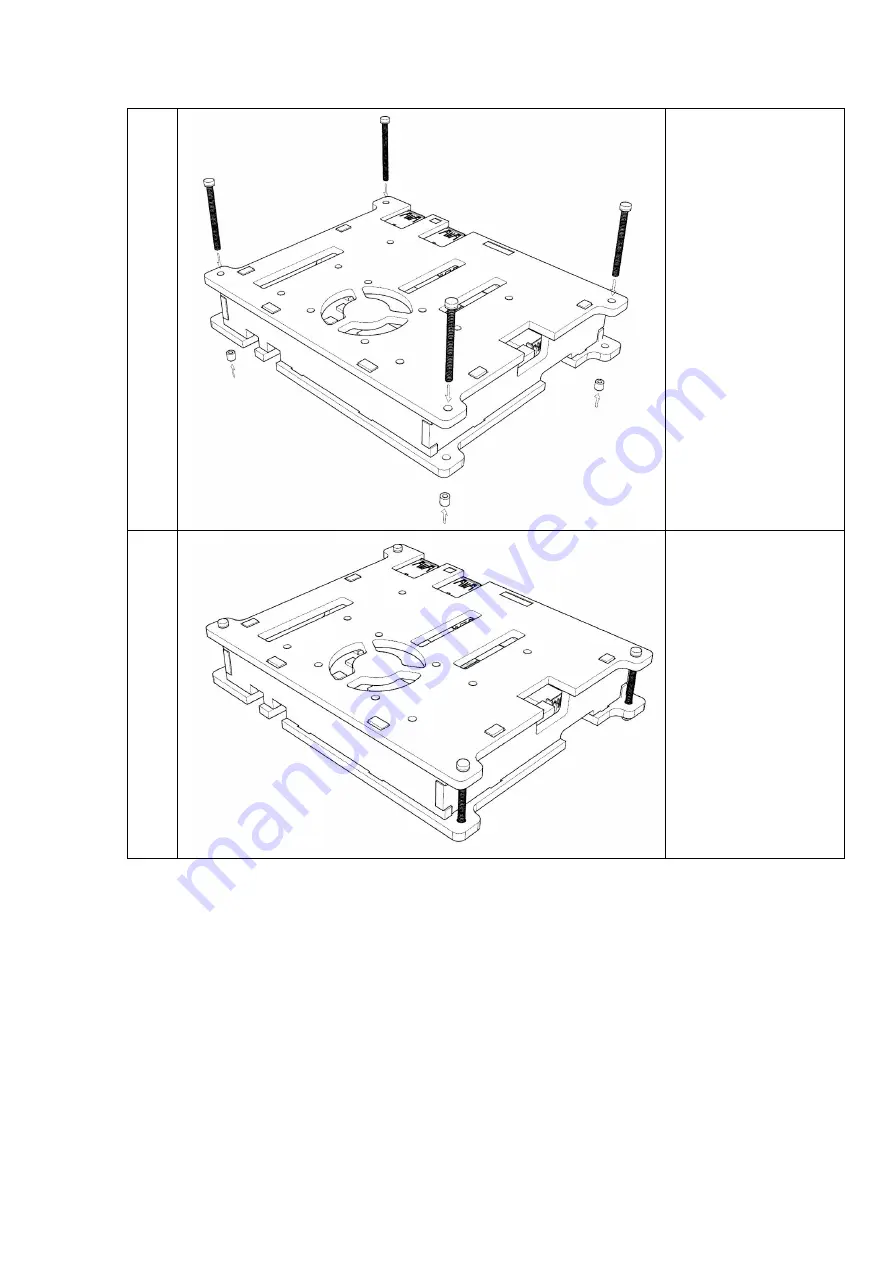
Pass the four case
screw ⑨ through the
upper and lower plates
of
the
housing
according
to
the
position and direction
shown in the figure;
Screw the four case
nuts ⑩
into the
corresponding screws
respectively according
to the position and
direction shown in the
figure
and
tighten
them.
7
Finish.
11.1.3 Other description
If you need to install and deploy other development board accessories or
peripherals on the housing (such as the eMMC memory card fan for the Obi MID-Light
3D camera, etc.), please refer to the installation instructions for the corresponding
accessories.
11.2 The power adapter
11.3 RTC
11.4 Touch module and LCD display
11.5 Microphone array ( Far field pickup algorithm , Noise reduction algorithm and
act)
Summary of Contents for P1
Page 1: ...1 Zora P1 DEVELOPMENT BOARD Zora P1 V1 0 電波法により5GHz帯は屋内使用に限ります ...
Page 6: ...6 1 8 Product size description 116 100mm ...
Page 13: ...13 e 2 Software interface English f Import firmware x img ...
Page 14: ...14 f 2 Software interface English g Click the start button enter burning state ...
Page 15: ...15 g 2 Software interface English h Complete firmware burning ...
Page 24: ...24 9 Hardware data of development board 9 1 Schematic diagram ...


