background image

Digital Video Security Systems

- 2 -

3D-DNR

 DAY & NIGHT COLOR CAMERA

About D-WDR/BLC/ 3D DNR

DNR DSP Chip

DNR
DSP Chip

DNR
DSP Chip

Privacy

Masking

Mirror

CCD Defect

Compensation

AE/AWB/AF

Sens-Up

Noise

Reduction

Motion

Detection

OSD IC

CPU

(16 Bit)

DNR

SDRAM

Line Lock

(Digital)

DISK SAVING

Digital Image Stabilizer

3D-DNR

Digital

R

eduction

Noi

se

Anti-Vandal

DAY & NIGHT

Resolution

Horizontal

DSP

0.00001 Lux

Illumination

Minimum

DNR

550

Wide Dynamic Range

Digital

WDR

ILBCT

IR

Backlight

Compensation

BLC

OSD

D-WDR(Digital Wide Dynamic Range)

550TV Lines

High Spotlight BLC Function

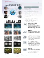
3D Filtering Method of Newly

Advanced DNR Function

D-WDR is a powerful and ultra advanced  technology
that captures cleaner and superior high Resolution pic-
tures even where images appear dark because there is 
a strong back light present.

The combination of a Sony Super HAD CCD image sen-
sor and DNR DSP provides an excellent resolution of 
550 TV lines.

Newly developed 3D filtering enhances Digital Noise 
reduction at low light levels. 3D Filtering of the Video 
Signal Optimises the Signal to Noise ratio, giving vastly 
improved low light visivility and a powerful Sens-Up 
function (up to 258 times magnification).

High Spotlight BLC Function is Especially Effective to
Read the Number Plate of the Vehicles in the Street or 
Parking Lot at Night Time. Especially Users Can Adjust 
and Select the Special Required Area to Observe the 
Target Object Under the Strong Spots of Light Exist.

Digital WDR OFF

3D-DNR OFF

Normal BLC

Standard Camera

Digital WDR ON

3D-DNR ON

HS BLC

550TV Lines Camera

550TV Lines

3D-DNR

OSD Control

Digital Zoom

HS BLC

Digital WDR

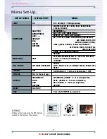
1. LENS

2. EXPOSURE

3. WHITE BAL

4. DAY NIGHT

5. 3DNR

6. SPECIAL

7. ADJUST

8. RESET

9. EXIT

SETUP

DC

ATB

COLOR

OFF

SHUTTER

BRIGHTNESS

AGC

SENS-UP

BLC

D-WDR

RETURN

EXPOSURE

1 / 60

                 48 

HIGH

AUTO

OFF

OFF

RET

1. CAM TITLE

2. D-EFFECT

3. MOTION

4. PRIVACY

5. SYNC

6. LANGUAGE

7. RETURN

SPECIAL

OFF

OFF

OFF

INT

ENGLISH

RET

- 1/3” Sony Super HAD CCD
- Up-Most High Resolution :
   Color - 550TV Line / B/W - 600TV Lines
- Built-In Next Generation 3D DNR with 3D Filter
- Max. Sens-Up (x258), 0.00001 Lux of Min. Illumination
- Convenient OSD control function
- x32 Digital Zoom
- Free Area Selectable function of BLC and MD
- Privacy Color Masking for 8 Area selection
- Camera OSD control 
- ICR-IR Infrared Cut Filter Removable(Option)
- Max 70% of Disk Saving Effect with Super DNR
- Negative Image Function 
- Digital Wide Dynamic Range Function(D-WDR)
- Dual Power(AC 24V / DC 12V)

DNR DSP Chip

DNR
DSP Chip

DNR
DSP Chip

Privacy

Masking

Mirror

CCD Defect

Compensation

AE/AWB/AF

Sens-Up

Noise

Reduction

Motion

Detection

OSD IC

CPU

(16 Bit)

DNR

SDRAM

Line Lock

(Digital)

DISK SAVING

Digital Image Stabilizer

3D-DNR

Digital

R

eduction

Noi

se

Anti-Vandal

DAY & NIGHT

Resolution

Horizontal

DSP

0.00001 Lux

Illumination

Minimum

DNR

550

Wide Dynamic Range

Digital

WDR

ILBCT

IR

Backlight

Compensation

BLC

OSD

Illumination

With an Incredibly Minimum Illumination of Amazing
0.00001Lux can Capture Good Images Even in
Extremely Low Light Conditions and Related Noises
are Significantly Reduced by the Ultra Advanced
DNR(Digital Noise Reduction) Technology.

Standard Image

Minimum Illumination Image

GENERAL FEATURES

Summary of Contents for R255VDIR/G

Page 1: ...Digital Video Security Systems 3D DNR DAY NIGHT COLOR CAMERA Anti Vandal Water Resistant 3D DNR DAY NIGHT CAMERA R255VDIR G R255VDIR W USER MANUAL 3 DNR OSD Camera...

Page 2: ...to alert the user to the presence of important operating and maintenance servicing instructions in the literature accompanying the appliance INFORMATION This equipment has been tested and found to com...

Page 3: ...ide ventilation whenoperating under high temperatures This is one of the most important parts of the camera Be careful not to leave fingerprints on the lens cover Do not install or use the camera in a...

Page 4: ...How to Install About 3D DNR Installation Sefety Instructions General Features Trouble Shooting Menu Set Up Menu Set Up Lens Set Up Exposure Back Light D WDR White Bal Day Night 3DNR Special Adjust Res...

Page 5: ...djust and Select the Special Required Area to Observe the Target Object Under the Strong Spots of Light Exist Digital WDR OFF 3D DNR OFF Normal BLC Standard Camera Digital WDR ON 3D DNR ON HS BLC 550T...

Page 6: ...Balance Electronic Shutter Speed Sense Up Gain Control 3 DNR D WDR Motion Detection Privacy Mirror Freeze Sharpness D N Selection Digital Zoom Blemish Compensation Power Power Consumption Lens Operati...

Page 7: ...UTO B W COLOR EXT ON Refer to the next page FACTORY DC LEVEL 0 100 Adjustable ON RANGE 0 100 Level Selectable OFF Save the SETUP Menu and exit SHUTTER FLK 1 60 1 250 1 500 1 2000 1 5000 1 10000 1 1000...

Page 8: ...n the locking screws and focus the camera Re tighten the locking screws Portable connector for easy installation of the camera A portable monitor can be connected to the camera allowing the operator t...

Page 9: ...power plug when still connected to the outlet Always disconnect the power by removing the plug from the power socket lf the camera emits a burning smell immediately disconnect it from the power sourc...

Page 10: ...ulting in enhanced surveilance images Disk Saving Effects Advanced 3DNR technology improves picture quality and saves hard drive space as less noise means much smaller file sizes much smaller than sta...

Page 11: ...FAULT LEFT RIGHT WIDTH TOP BOTTOM HEIGHT RETURN D WDR OFF INDOOR OUTDOOR RETURN ATW AWB MANUAL R Gain 0 100 Level Selectable B Gain 0 100 Level Selectable AWC SET SHARPNESS RANGE 0 31 Level Adjustable...

Page 12: ...LECT AREA 1 AREA DISPLAY ON OFF LEFT RIGHT 0 100 Level Adjustable WIDTH 0 100 Level Adjustable TOP BOTTOM 0 100 Level Adjustable HEIGHT 0 100 Level Adjustable SENSITIVITY 0 40 Level Adjustable RETURN...

Page 13: ...displayed on the monitor 2 Move and select the required function using the Up and Down button Move the arrow indicator Up or Down to select the desired feature by pressing the Up or Down button SETUP...

Page 14: ...the setting move the arrow indicator to EXIT and press the SET button to EXIT 1 Move the arrow indicator to LENS using the Up and Down buttons on the Set Up menu screen 2 Select the desired lens type...

Page 15: ...ETURN 100 This function is used to select Automatic or Manual shutter speed control 1 On the Set Up menu screen select EXPOSURE by using the Up or Down button 2 Select the desired shutter mode by pres...

Page 16: ...FLK Brightness just can operate when selected the Manual mode Option When selected DC mode brightness will be disabled AGC AUTO GAIN CONTROL A higher gain increases brightness but also increases any n...

Page 17: ...e brightness by increasing or decreasing the shutter speed x2 x258 The higher the level the brighter the image becomes but it is possible that an after image ghosting could appear When SENS UP is acti...

Page 18: ...on from 0 7 cells Move the arrow indicator to select the HEIGHT of cells to increase or decrease by using the Left Right button from 0 7 cells Move the arrow indicator to the LEFT RIGHT and TOP BOTTOM...

Page 19: ...vity by selecting between 0 8 DEFAULT Press the Default to return to the factory default when input the wrong data HSBLC OFF HSBLC ON Move the arrow indicator to select the WIDTH of cells to increase...

Page 20: ...n on the EXPOSURE menu screen 2 Select the desired feature by using the Left or Right button EXPOSURE SHUTTER BRIGHTNESS AGC SENS UP BLC D WDR RETURN 1 60 LOW BLC OFF D WDR When there are simultaneous...

Page 21: ...White Balance Normal setting when the colour temperature range is from 1 800 K to 10 500 K Ex a fluorescent lamp or outdoors AWB The White Balance is automatically adjusted in a specific environment A...

Page 22: ...s SETUP LENS EXPOSURE WHITE BAL DAY NIGHT 3DNR SPECIAL ADJUST RESET EXIT DC ATW COLOR ON COLOUR The picture is always displayed in colour AWB The White Balance is automatically adjusted in a specific...

Page 23: ...ed between 0 100 E LEVEL The end level can be adjusted between 0 100 1 Move the arrow indicator to 3DNR by using the Up and Down button 2 Select whether or not to activate 3DNR by using the Left and R...

Page 24: ...Down button 1 CAM TITLE When input the Camera ID is displayed on the monitor 1 1 Move the arrow indicator to CAMERA ID using the Up or Down button on the SETUP menu screen 1 2 Set to ON using the Left...

Page 25: ...CAMERA TITLE is set to OFF the CAMERA TITLE is not displayed on the monitor 1 4 The CAMERA TITLE can be up to 15 alphanumeric characters in length Move the cursor to choose an alphanumeric character C...

Page 26: ...haracters from left to right and repeat the above steps to input the characters again 1 5 To select the position where the Camera ID should be displayed on the screen Move the cursor to POS and press...

Page 27: ...nfirm the position CAM1 2 D EFFECT Move the cursor to D EFFECT and press the SET button to set the other image functions 2 1 FREEZE Image freezing or moving Image SPECIAL D EFFECT 1 CAM TITLE OFF 2 D...

Page 28: ...he pan range can be controlled between 10 100 TILT The pan range can be controlled between 10 100 V FLIP Flip the image vertically on the screen ROTATE Flip the horizontal image vertically on the scre...

Page 29: ...ed use the Up or Down botton to access the MOTION menu AREA SELECT Determines whether the MD area selected AREA 1 2 3 4 Move the arrow indicator to select the HEIGHT of cells to increase or decrease b...

Page 30: ...Y Hide an area you want to hide on the screen 4 1 When the SPECIAL menu screen is displayed press the Up and Down buttons to set to PRIVACY 4 2 Set up the area mode using the 4 direction buttons AREA...

Page 31: ...TOM to select the desired area positon by using the LEFT or RIGHT button Move the arrow indicator to COLOR to select the desired color of each area cells by using the Left Right button between the 15...

Page 32: ...an distort the image or cause noise Select BLUE or RED to increase or decrease the value of R Gain RED and B Gain BLUE while monitoring the color of the image RETURN Move the arrow indicator to RETURN...

Page 33: ...e 75 Hi z Has MOTION DET been set to ON in the menu Has MD AREA been properly defined Check that the AGC setting in the EXPOSURE menu is t set to OFF Check the EXPOSURE menu and make sure SHUTTER is s...

Page 34: ...Digital Video Security Systems 31 3D DNR DAY NIGHT COLOR CAMERA MEMO...

Page 35: ...Digital Video Security Systems 32 3D DNR DAY NIGHT COLOR CAMERA MEMO...

Page 36: ...T S MICRO TECH INC 17109 Gale Ave City of Industry CA 91745 U S A TEL 626 839 8998...

Reviews: