Zodiac EziSalt Installation Manual Download Page 12

Page 13

Page 12

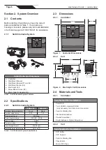
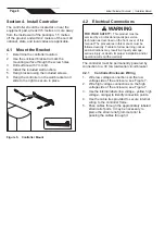
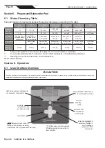
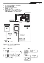
EziSalt Saltwater Chlorinator   |   Installation Manual

Cover mode is activated with a open/close 

dry contact, check that the installed cover is 

compatible and connected to the chlorinator.
Cover mode will automatically be activated when 

the cover is closed. The Cover mode message and 

the output percentage are displayed on the screen. 

23:04 ON

COVER MODE  10%

Cover mode will stop as soon as the cover is 

completely open.

6.2.7 

Locking the Controller

The controller can be locked, thus deactivating 

the buttons on the user interface panel. 

Simultaneously press and hold the   and   

buttons for 3 seconds. This function can be 

accessed from any screen/menu.
Locking the controller automatically returns the user to 

the home screen. To unlock the controller, press and 

hold the   and   buttons for another 3 seconds.

Section 7.  Installing and Assigning 

Equipment
7.1  Filter Pump

NOTE:

 Suitable for any manually-operated variable 

speed pump (i.e., any pump that does not 

require a communication cable), you must set 

the pump configuration to single speed.

1.  Disconnect power from the chlorinator and 

remove the cover and lower housing. 

2. 

Connect the filter pump to the controller at 

the pump connection point in the high voltage 

raceway. 

3.  Replace the lower housing and cover.

4.  Plug the pump into the socket in the base of 

the chlorinator.

7.1.1 

Quick Clean

Quick Clean is a backwash mode and is used 

to quickly start/stop the filter pump in order to 

backwash the filter. 
1. 

Select YES to activate filtration.

2. 

Select NO to stop filtration.

For safety reasons, the chlorination is stopped 

during the backwash mode. To avoid emptying the 

pool, the backwash mode automatically stops after 

5 minutes. 

7.2  Aux/Lights

The chlorinator is capable of controlling devices in 

addition to the filter pump. The equipment must be 

connected to the chlorinator using the appropriate 

auxiliary line:
Aux 2: for equipment connected to the low voltage 

supply (12/24 V).
The following functions are available in the 

AUX/LIGHTS menu:

●  Turn the lights or aux equipment on/off


●  Program a timer (See section 7.3 for details)

NOTE

:  To control the light transformer, an additional 

switching box is required. Please contact your 

local pool care professional for this relay box, 

item code WW000222.

1.  Remove the lower housing and cover to 

expose the connection bar.

2.  Run the supplied low voltage 2 core wire 

through the rubber grommet from the relay 

switch box into the terminal bar marked  

‘AUX 2’.

3.  Push the red pin connector into the relay 

switch.

Summary of Contents for EziSalt

Page 1: ...installation codes Before installing this product read and follow all warning notices and instructions that accompany this product Failure to follow warning notices and instructions may result in pro...

Page 2: ...GE READING WITH CLEAN FILTER PUMP MODEL HORSEPOWER FILTER MODEL CONTROL PANEL MODEL SERIAL NUMBER NOTES EQUIPMENT INFORMATION RECORD For full warranty terms and conditions and to register your warrant...

Page 3: ...on 5 Prepare and Balance the Pool 10 5 1 Water Chemistry Table 10 Section 6 Operation 10 6 1 User Interface Overview 10 6 2 Initial start Up 11 Section 7 Installing and Assigning Equipment 12 7 1 Filt...

Page 4: ...ult Lower water temperatures are recommended for young children and when spa use exceeds 10 minutes b Since excessive water temperatures have a high potential for causing fetal damage during the early...

Page 5: ...s of a spa or hot tub The use of alcohol drugs or medication can greatly increase the risk of fatal hyperthermia in hot tubs and spas Water temperature in excess of 38 C may be hazardous to your healt...

Page 6: ...lorine production 24 g h 40 g h Nominal output amps 5 0 A 7 2 A Required salt level 4000ppm Power supply voltage 240 VAC 50 Hz Electric power 200 W Protection index IP43 Flow through the cell Min 80 L...

Page 7: ...s 5 Ensure the o rings are seated properly on the adapters 6 Secure the cell to the plumbing by tightening the unions hand tight DO NOT OVERTIGHTEN 7 Double check cell orientation The cell inlet is cl...

Page 8: ...serviced by a professional pool spa service technician as described on the front cover of this manual The procedures in this manual must be followed exactly Failure to follow warning notices and inst...

Page 9: ...DRED Function Demand Response Enabled Device for Australia only COVER Input Pool cover contact lower the chlorine production dry contact cover open open contact cover closed closed contact SLAVE Inpu...

Page 10: ...l pool with water from the mains water supply Do not use rain water or well water Do not add salt directly into the skimmer Do not initiate electrolysis until salt has fully dissolved Reading is True...

Page 11: ...nected to the controller the filter pump will operate in Boost mode also The controller s operating times including filtration schedules are temporarily ignored for the duration of the Boost mode This...

Page 12: ...to the controller at the pump connection point in the high voltage raceway 3 Replace the lower housing and cover 4 Plug the pump into the socket in the base of the chlorinator 7 1 1 Quick Clean Quick...

Page 13: ...utlet on relay switch box Relay switch box plugs directly into 240VAC for power Low voltage 2 core cable wires directly to red terminal on relay switch and into AUX 2 terminal on power pack Pool Light...

Page 14: ...tration and or chlorination will run continuously The filtration operating times must be sufficient to correctly treat the water Example single speed pump In Season filtration time 8 10 hours per day...

Page 15: ...30 04 30 The T symbol is displayed in the upper right hand corner of the LCD display on the home screen if the programming is valid The P symbol is displayed in the upper right hand corner of the LCD...

Page 16: ...ring detail Boost and Low modes will remain operational from the controller However SWC programs will be deactivated Chlorination output will be maintained at 100 1 Connect the external controller at...

Page 17: ...es 7 Turn pump and controller on 8 Confirm chlorine output and settings on the power pack Timer programs will be automatically retained Unscrew and Remove Barrel Unions Figure 10 Cleaning the Electrod...

Page 18: ...quire repair replacement before further serious damage is sustained A small amount of regular care and attention to your pool equipment will help ensure long life and trouble free performance To prote...

Page 19: ...cell etc Clean cell plates See Section 9 for cleaning instructions Replace the cell LOW CONDUCTIVITY SALTS indicator lit For models with a temp sensor this error can be caused by low conductivity Lack...

Page 20: ...registered trademark of Zodiac International S A S U used under license All other trademarks are the property of their respective owners H0707600_REVA Fluidra Group Australia Pty Ltd 219 Woodpark Roa...

Reviews: