XPLC108E Motion Controller User Manual V1.5
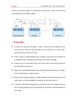
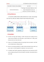
parties are connected together. In CAN bus left and right sides, connect a 120
Ω
resistor
respectively (please see below graphic).
→
Wiring Notes:
⚫
As above, the daisy chain topology is used for wiring (the star topology structure
cannot be used). When the use environment is ideal and there are no many nodes,
the branch structure also can be used.
⚫
Please connect a 120Ω terminal resistor
in parallel to each end of the CAN bus for
matching the circuit impedance and ensuring communication stability.
⚫
Please be sure to connect the public ends of each node on the CAN bus to prevent
the CAN chip from burning out.
⚫
Please use STP (Shielded Twisted Pair), especially in bad environments, and make
sure the shielding layer is fully grounded.
⚫
When on-site wiring, pay attention to make the distance between strong current and
weak current, it is recommended for the distance to be more than 20cm.
⚫
It should be noted that the equipment grounding (chassis) on the entire line must be
good, and the grounding of the chassis should be connected to the standard factory
ground pile.
Summary of Contents for XPLC108E
Page 1: ......

