ECI3828 Network Motion Control Card User Manual V1.5
9
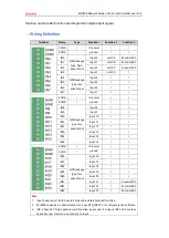
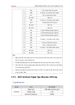
DIR+
Servo or step direction
10
GND
5V power (-) of pulse/encoder signal
11
PUL-
Servo or step pulse output -
12
Reserved
Reserved
13
GND
5V power (-) of pulse/encoder signal
14
OVCC
Positive pole of IO 24V power
15
Reserved
Reserved
16
Reserved
Reserved
17
EA+
Encoder differential input signal A+
18
EB+
Encoder differential input signal B+
19
EZ+
Encoder differential input signal Z+
20
GND
5V power (-) of pulse/encoder signal
21
GND
22
DIR-
Servo or step direction output -
23
PUL+
Servo or step pulse
24
GND
5V power (-) of pulse/encoder signal
25
Reserved
Reserved
26
Reserved
Reserved
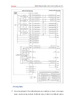
Note:
Alarm input and axis enable output are used as general input and output at the same time,
when it is output, output small current.
ECI3828 differential pulse axis and differential encoder input are only for axis 0 and axis 1.
Axis 2 and axis 3 are low-speed single-ended pulse interface OUT2-3, which can be modified
to take effect through ATYPE.
High-speed single-end encoder input of axis 2 is IN0-2, low-speed single-end encoder input
of axis 3 is IN21-IN23.
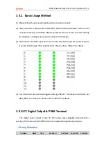
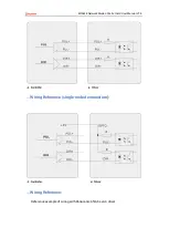
3.9.1.
AXIS Interface Signal Specification & Wiring
→
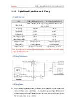
Specification:
Signal
Item
Description
PUL/DIR
Signal type
Differential output signal
Voltage range
0-5V
Maximum frequency
10MHz
Summary of Contents for ECI3828
Page 1: ......


