ZSSC5101
Evaluation Kit Description
Kit Description
April 17, 2015
© 2015 Zentrum Mikroelektronik Dresden AG
— Rev. 1.00
All rights reserved. The material contained herein may not be reproduced, adapted, merged, translated, stored, or used without the
prior written consent of the copyright owner. The information furnished in this publication is subject to changes without notice.
18 of 25
1. Click the
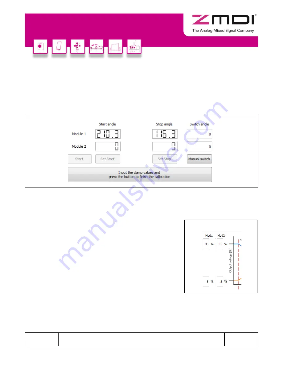
“Start” button on the “Angle Calibration” tab and wait until the “Set Start” button becomes active.
2. Move the magnet to the start position (note that this is the maximum clockwise position when looking at
t
he sensor from the top). Click “Set Start.” This stores the start position, and then the “Set Stop” button
becomes active.
3. Rotate the magnet to the stop position (when looking at the sensor from the top, rotate the magnet
counterclockwise to the stop p
osition) and click “Set Stop.” This stores the stop position.
Figure 4.10
Setting the Angle Range with the “Angle Calibration” Tab
4. Optional: The switch angle, which is the angular position where the analog output returns from Vout,max
to Vout, min, can be manually entered
for each module in the “Switch angle” entry fields. Then click
“Manual switch” to confirm the entry, which stores the value in EEPROM. If no value is entered, it will be
calculated automatically.
5. Optional: Enter the minimum and maximum clamping values at the
two mechanical stop positions as percentages of VDD in the entry
fields adjacent to the graph in the upper left section of the tab.
Alternatively, the default values that are already displayed can be
used. See Figure 4.11, which illustrates the example default values
Vmin = 5% VDD and Vmax = 95% VDD.
6. To complete the angle calibration, click the large button at the
bottom
of the tab, which has the label “Input the clamp values and
press the button to fin
ish the calibration.” (See Figure 4.10.) When
the angle programming is completed, this button becomes grey
and its label changes to “Done.”
Figure 4.11 Clamping Values


