background image

4  SBTL5000 series installation guide 
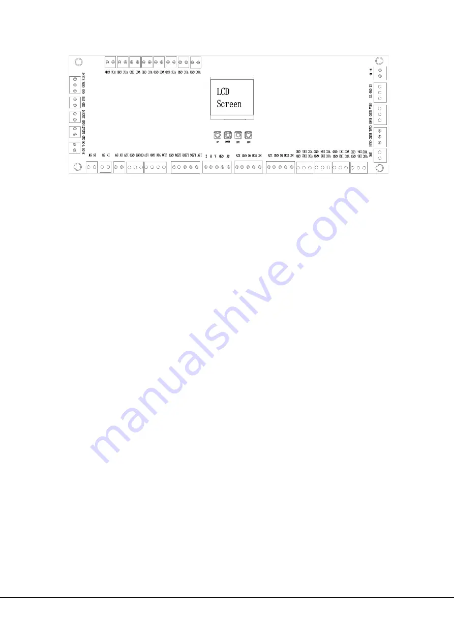
 

Figure 4-1 

4.2


Button introduction 

UP: to move up menu item or increase the value.  

DOWN: to move down menu item or decrease the value. 

ENT: to enter menu setting item or confirm the current modified value. 

ESC: to return to the previous menu or to cancel the current operation. 

4.3


Menu operation 

Press the ENT button, enter the password input interface, 

the default password is: ‘UP, 

UP, DOWN, DOWN, DOWN, DOWN

. If any step fails please press the ESC button to get 

back. After entering the menu press 

UP

 or 

DOWN

 to choose a menu item and then 

press 

ENT

 to enter the interface and adjust function or value. 


Attention:

  The product has been inspected and debugged before sending  out of 

factory, in order to ensure that before normal usage, the system is safe and reliable. It is 
also must to check the system again after installing in the field. All the above operation 

should be operated by professional and parameters setting of the system shouldn’t be 
changed without permission. 

Summary of Contents for SBTL5000 series

Page 1: ...Installation Guide Swing Barrier SBTL5000 series Applicable Model SBTL5000 5200 5011 5211 5022 5222 Version 1 0 Date Jan 2018 ...

Page 2: ...d three core power extension wire M12 expansion screw included C Put the connection wire of devices into tube before laying them underground D Power wire and signal wire should be set separately for distinguishing strong and weak power It is recommended that the wiring is to be done by a professional and the device must be connected to the ground SBTL5000 installation holes and cabling positions a...

Page 3: ...n connect the wires between master and slave devices As shown in below Figure 2 2 5 core signal 2 core 24V power 3 Test with temporary cable ensure that ground wire of AC power was connected to cabinet 4 Turn on the air switch to test whether the device is working properly wait for 10 seconds for the gate to complete self test program At the same time check whether or not the indicator light worki...

Page 4: ...t according to the following wiring diagram Figure 3 1 4 Menu Operation 4 1 Function of control board A After connecting to power the LCD screen on control board will displays default state which is current Work Mode B There are 4 buttons UP DOWN ENT ESC below the LCD screen IR L IR1 IR R IR4 AP L IR2 AP R IR3 IR1 IR4 at the bottom IR2 IR3 on the top LED light LED light ...

Page 5: ...assword is UP UP DOWN DOWN DOWN DOWN If any step fails please press the ESC button to get back After entering the menu press UP or DOWN to choose a menu item and then press ENT to enter the interface and adjust function or value Attention The product has been inspected and debugged before sending out of factory in order to ensure that before normal usage the system is safe and reliable It is also ...

Page 6: ...etting and the 5 core 2 core connection line 3 Barrier open after a long time no closing Check whether the time of the opening is too long or the IR sensor is covered by others 4 Motor doesn t rotating or the resistance too great or belt loosen If the motor working properly but the rotated angle not enough which may caused by belt loosen If can t solve it try to increase the value of twelfth menu ...

Reviews: