background image

PB3000 Installation Guide 


Chapter 3 Boom Installation


1) 

Take out the booms. 

2) 

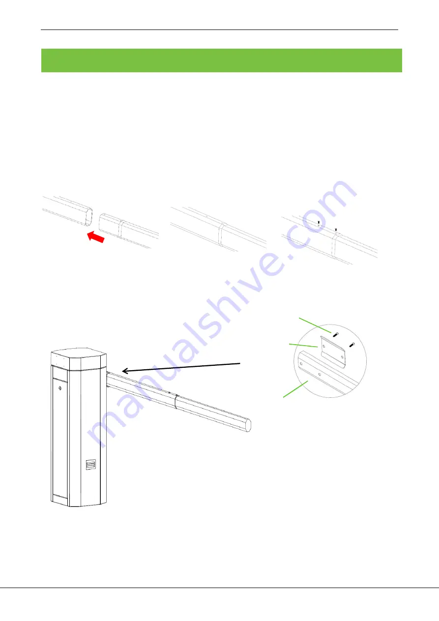
Install the booms. (If your purchase is PB3010L/R, there will be only one boom. If your purchase is PB3030L/R 

or PB 3060L/R there will be a main boom and a vice boom which need to be connected together. See figure 

3-1.) 

3) 

Putting the vice boom insert into the main boom, then fastened by 2 screws. 

4) 

Installing the boom to the chassis, as shown in figure 3-2. 


Figure 3-1 


Figure 3-2 Installing the Boom to the Chassis 


Connect  the  main boom with vice together by 2 screw


Screw 

Iron piece

Boom 

Summary of Contents for PB3000 Series

Page 1: ...Installation Guide PB3000 ...

Page 2: ...PB3000 Installation Guide 1 Contents Chapter 1 Cable Embedding 1 Chapter 2 Cabinet Installation 2 Chapter 3 Boom Installation 3 Chapter 4 Control board introduction 4 Chapter 5 Troubleshoot 5 ...

Page 3: ... a tool to open a cable tray on the ground see figure 1 1 Figure 1 1 Cable embedding The power wire is wrapped and protected using the wire sleeve when laid out under the ground the strong current should be separated from the weak current Control room Screw pad Ground Ground Cabinet Expansion bolt 4 M12 Base concrete A standard power wire RVV3 1 0 A signal line RVV4 0 5 ...

Page 4: ...cabinet 2 Drive four expansion bolts into the Bolt Holes Dimensioning as shown in figure 2 1 3 Open the access door and install the parking barrier 4 Install screw pads and use a wrench to tighten nuts as shown in figure 2 2 5 Close the access door Figure 2 1 Figure 2 2 Screw pad Ground Ground Base concrete Chassis Expansion bolt ...

Page 5: ...030L R or PB 3060L R there will be a main boom and a vice boom which need to be connected together See figure 3 1 3 Putting the vice boom insert into the main boom then fastened by 2 screws 4 Installing the boom to the chassis as shown in figure 3 2 Figure 3 1 Figure 3 2 Installing the Boom to the Chassis Connect the main boom with vice together by 2 screw Screw Iron piece Boom ...

Page 6: ...top button on control board until D9 red light flashes one time All the registered transmitters will be deleted after successful operation Register the transmitter Press K4 setting button until D8 yellow light flashes Hold on K4 press any button on transmitter until D9 red light flash one time Maximum 7 different code transmitters can be registered 2 Interface of the Extension board Control board ...

Page 7: ... the boom shakes during falling or lifting adjust position C The shaking that occurs during lifting is caused by the overlarge spring force In this case loosen the screws If the boom shakes during falling tighten the screws See Figure 5 2 3 Use the motor handle to lift the boom in the case of a power failure See Figure 5 3 Figure 5 1 Figure 5 2 Figure 5 3 Position C Position A Position B Handle ...

Reviews:

Related manuals for PB3000 Series