background image

3

Door Preparation

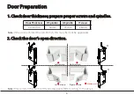
1. Check door thickness; prepare proper screws and spindles.

Note: 

Please install the mortise (H) and strike plate (M) according to the above 

H

H

H

H

Left inward            Right inward

Left outward         Right outward

2. Check the door’s open direction.

Door Thickness

D Spindles

G Spindle

I Screws

40 - 50 mm

30 mm

75 mm

25 mm

Note: 

If the door is thicker than 40-50 mm,

this lock shall not be applicable.

Standpoint

Summary of Contents for LH6500

Page 1: ...Installation Instruction Version 1 0 Date Jun 2018 LH6500 ...

Page 2: ...Lock Diagram Before Installation A B D C H L M P R E I J Q N O F 1 K G ...

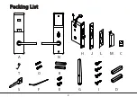
Page 3: ...Packing List 2 A N H J L M C S T O B F E G I D ...

Page 4: ...ortise H and strike plate M according to the above H H H H Left inward Right inward Left outward Right outward 2 Check the door s open direction Door Thickness D Spindles G Spindle I Screws 40 50 mm 30 mm 75 mm 25 mm Note If the door is thicker than 40 50 mm this lock shall not be applicable Standpoint ...

Page 5: ...es not included are required Non alkaline and rechargeable batteries ARE NOT RECOMMENDED 5 Do not remove batteries when the lock is in working state 6 When battery power is low the lock will beep to remind user to renew the batteries Please do not mix up positive and negative while replacing battery 7 Avoid contacting with corrosive substances and do not hang objects on the handle 8 The software w...

Page 6: ...hickness 40 50 mm backset 62 5 mm 2 Remove the mortise latch plate J 1 Drill holes on the door Note 1 Align the template along the vertical center line of the mortise H at the desired handle height and tape it to door Note 2 Mark the holes first then start drilling H K J ...

Page 7: ...6 3 Install mortise H I I H K J K ...

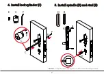
Page 8: ...7 5 Install spindle D and stud B D 4 Install lock cylinder C F C E Note Ensure the two triangles are in horizontal alignment A B B D E C C F E ...

Page 9: ...8 7 Install spindle G and D D G 6 Install outdoor unit A A G D ...

Page 10: ...9 9 Install the battery P and battery cover Q N 8 Install indoor unit N P O Q R ...

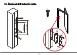
Page 11: ...10 10 Mark and drill holes for strike 3 mm 22 mm 125 mm 89 mm 25 mm I M L I ...

Page 12: ...11 Step1 Remove the cover on the key hole with a hook T Step2 Insert mechanical key S into the key hole and rotate it at 90 11 Test Lock by mechanical key S T S ...

Page 13: ...erence will not occur in a particular installation If this equipment does cause harmful interference to radio or television reception which can be determined by turning the equipment off and on the user is encouraged to try to correct the interference by one or more of the following measures Reorient or relocate the receiving antenna Increase the separation between the equipment and receiver Conne...

Page 14: ...www zkteco com Copyright 2018 ZKTECO CO LTD ZKTeco Logo is a registered trademark of ZKTeco or a related company All other product and company names mentioned are used for identification purposes only and may be the trademarks of their respective owners All specifications are subject to change without notice All rights reserved ...

Reviews: