background image

3

ProCapture-T & ProRF-T and ZKBioSecurity 3.0 Quick Start Guide

On Using Face Recognition Device

1. 

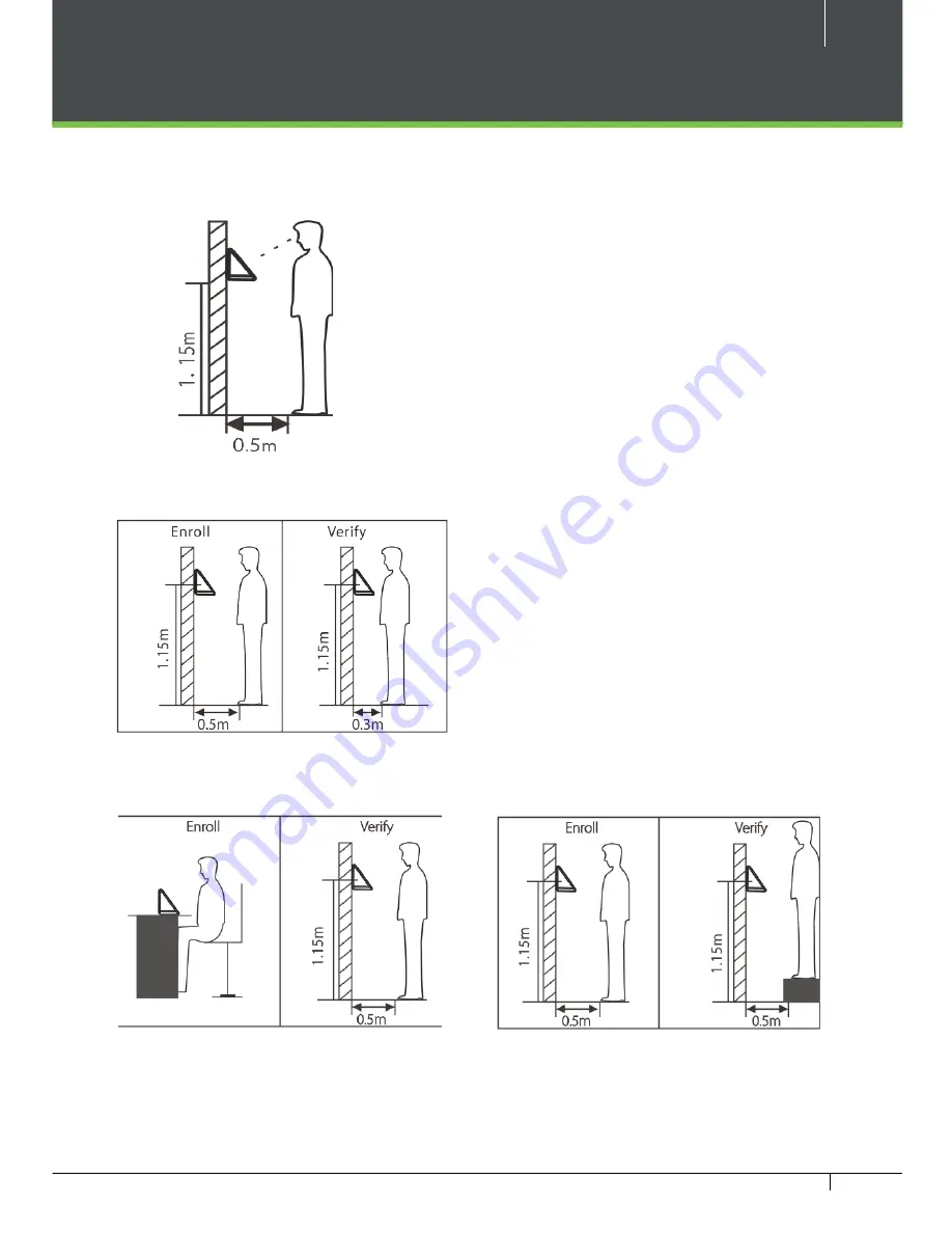
Recommended Standing Position


For user heights between 1.5m to 1.8m, it is  


      recommended to install the device at 1.15m above  


      ground (may be modified according to user 


      average height).


a. 

Recommended Registration and Verification Position


b. 

Factors Affecting the Preciseness of Verification


Non-identical registration    

             Non-identical registration 


 and verification gestures   

              and verification height

During registration and verification pro-
cedures, the position of device should 
not be changed to prevent deduction in 
verification preciseness. If it is necessary 
to move the device, its vertical height 
should not be changed. 

Summary of Contents for ProCapture-T

Page 1: ...QuickStartGuide ProCapture T ProRF T ZKBioSecurity3 0 ...

Page 2: ...Face Recognition Device 3 Device Overview 5 Product Dimensions Installation 7 Power Connection 8 Ethernet Connection 9 RS485 Connection 10 Lock Relay Connection 11 Wiegand Output Connection 13 Standalone Installation 14 Device Operation 15 ZKBioSecurity Software Installation and Setup starts at Page 18 ...

Page 3: ...CRTs TVs monitors or speakers may dam age the device Do not place the device next to heating equipment Be careful not to let liquid like water drinks or chemicals leak inside the device Do not let children touch the device without supervision Do not drop or damage the device Do not disassemble repair or alter the device Do not use the device for any other purpose than specified Clean the device of...

Page 4: ... to user average height a Recommended Registration and Verification Position b Factors Affecting the Preciseness of Verification Non identical registration Non identical registration and verification gestures and verification height During registration and verification pro cedures the position of device should not be changed to prevent deduction in verification preciseness If it is necessary to mo...

Page 5: ...om device and verification distances from device 2 Registration a During registration it is required to adjust your upper body to fit your eyes into the green frame on the screen b During verification it is required to show your face in the center of the screen and fit your face into the green frame in the screen On Using Face Recognition Device ...

Page 6: ... card function ProCapture T ProRF T ProCapture T Camera 2 4 inch Color Screen Touch Keypad Door Bell LED Indicator Fingerprint Card Reader Card Reader Area Area USB Slot Reset Button ProRF T Left side bottom view is common for both the devices Security Screw Holes for securing the device onto the back plate Speaker ...

Page 7: ... 12V BUT BELL BELL RJ45 3 GLED AL IWD0 NO1 GND RJ45 2 IWD1 NC1 GND SEN RJ45 6 BEEP AL Ethernet Alarm Wiegand Wiegand RS485 Lock Bell Power Sensor Button RXD GND WD1 TXD 485A GND 485B WD0 12V GND GND AUX Auxilliary RS232 Power In Beep Green LED Red LED RLED RJ45 1 COM1 12V BUT BELL BELL RJ45 3 GLED AL IWD0 NO1 GND RJ45 2 IWD1 NC1 GND SEN RJ45 6 BEEP AL Ethernet Alarm Wiegand Wiegand RS485 Lock Bell...

Page 8: ...in 186 5mm 3 43in 87mm 7 70in 195 5mm ProCapture T 0 51in 13mm 1 2 ProCapture T Fix the back plate onto the wall using wall mounting screws Note We recommend drilling the mounting plate screws into solid wood i e stud beam If a stud beam cannot be found use supplied drywall plastic anchors Use security screws to fasten the device to back plate Insert the device to back plate ...

Page 9: ... 12V BUT BELL BELL RJ45 3 GLED AL IWD0 NO1 GND RJ45 2 IWD1 NC1 GND SEN RJ45 6 BEEP AL Ethernet Alarm Wiegand In Output Wiegand Output RS485 Lock Bell Power Out Sensor Button RXD GND WD1 TXD 485A GND 485B WD0 12V GND GND AUX Auxiliary In RS232 Power In RLED RJ45 1 COM1 12V BUT BELL BELL RJ45 3 GLED AL IWD0 NO1 GND RJ45 2 IWD1 NC1 GND SEN RJ45 6 BEEP AL Ethernet Alarm Wiegand In Output Wiegand Outpu...

Page 10: ... NO1 GND RJ45 2 IWD1 NC1 GND SEN RJ45 6 BEEP AL Ethernet Alarm Wiegand In Output Wiegand Output RS485 Lock Bell Power Out Sensor Button RXD GND WD1 TXD 485A GND 485B WD0 12V GND GND AUX Auxiliary In RS232 Power In RJ 45 1 2 3 4 5 6 7 8 RJ45 6 Yellow RJ45 3 Green RJ45 2 RJ45 1 Black Red DESCRIPTION WIRE ZKBioSecurity Ethernet cable Network Cable Apator ...

Page 11: ...e length is more than 200 meters or 600 ft the number 6 switch should be ON as below RLED RJ45 1 COM1 12V BUT BELL BELL RJ45 3 GLED AL IWD0 NO1 GND RJ45 2 IWD1 NC1 GND SEN RJ45 6 BEEP AL Ethernet Alarm Wiegand In Output Wiegand Output RS485 Lock Bell Power Out Sensor Button RXD GND WD1 TXD 485A GND 485B WD0 12V GND GND AUX Auxiliary In RS232 Power In Do not use 12V Red GND Black IWD1 IWD0 BEEP Pur...

Page 12: ...l one FR107 diode equipped in the package to prevent the self inductance EMF from affecting the system Do not reverse the polarities RLED RJ45 1 COM1 12V BUT BELL BELL RJ45 3 GLED AL IWD0 NO1 GND RJ45 2 IWD1 NC1 GND SEN RJ45 6 BEEP AL Ethernet Alarm Wiegand In Output Wiegand Output RS485 Lock Bell Power Out Sensor Button RXD GND WD1 TXD 485A GND 485B WD0 12V GND GND AUX Auxiliary In RS232 Power In...

Page 13: ...ay Black Red Do not use DESCRIPTION WIRE AL NC1 COM1 NO1 BUT GND SEN BELL BELL GND AUX AL Sensor GND RLED RJ45 1 COM1 12V BUT BELL BELL RJ45 3 GLED AL IWD0 NO1 GND RJ45 2 IWD1 NC1 GND SEN RJ45 6 BEEP AL Ethernet Alarm Wiegand In Output Wiegand Output RS485 LOCK Bell Power Out Sensor Button RXD GND WD1 TXD 485A GND 485B WD0 12V GND GND AUX Auxiliary In RS232 Power In Device Sharing Power with the L...

Page 14: ... Connection RLED RJ45 1 COM1 12V BUT BELL BELL RJ45 3 GLED AL IWD0 NO1 GND RJ45 2 IWD1 NC1 GND SEN RJ45 6 BEEP AL Ethernet Alarm Wiegand In Output Wiegand Output RS485 Lock Bell Power Out Sensor Button RXD GND WD1 TXD 485A GND 485B WD0 12V GND GND AUX Auxiliary In RS232 Power In ...

Page 15: ...apture T ProRF T and ZKBioSecurity 3 0 Quick Start Guide Standalone Installation Sensor Lock ALARM EXIT No Touch Exit Button Doorbell ProCapture T Ethernet ZKBioSecurity ZKBioSecurity Rs485 Fingerprint Reader ...

Page 16: ...hoto and setting access control role Ethernet Settings Press icon to enter the Main Menu Comm Ethernet The parameters below are the system default values Please adjust them according to the actual network IP Address 192 168 1 201 Subnet Mask 255 255 255 0 Gateway 0 0 0 0 DNS 0 0 0 0 TCP COMM Port 4370 DHCP Dynamic Host Configuration Protocol which dynamically allocate IP addresses for clients via ...

Page 17: ...ntrol To gain access the registered user must meet the following conditions 1 User s access time must fall within either user s personal time zone or group time zone 2 User s group must be in the access combo when there are other groups in the same access combo verification of members of those groups are also required to unlock the door Access Control Options To set parameters of the lock and othe...

Page 18: ...issue or a mildly wet cloth If a fingerprint is too dry blow on the finger and retry 2 Invalid time zone is displayed after verification Contact Administrator to check if the user has the privilege to gain access within that time zone 3 The Tamper Alarm rings Check whether the user privilege is set correctly Check whether the lock wiring is correct Check whether anti passback mode is in use In ant...

Page 19: ...n Setup It is recommended to install software version 3 0 3 0 or above Downloading 19 Installation 20 Adding Device 22 Creating aTime Zone 24 Creating an Access Level 25 Enrolling Personnel 26 Wiegand Format 28 Add Delete Personnel to Access Level 29 Real Time Monitoring 30 Exporting Reports 31 ...

Page 20: ... Quick Start Guide Downloading 1 Go to http www zkteco com product ZKBioSecurity3 0_421 html 2 Download the latest software and related files as required 3 Once downloaded extract the rar file to a new folder 4 Click on setup to begin installstion ...

Page 21: ...nts to install the software Click Continue if all tests are passed else check the issues and re test 2 Add an open port Default 8088 or ask a network administrator for an open port Note Stanalone device doesn t support https 3 Click the check box to add firewall exception for this port Installation ...

Page 22: ...Installation 4 Select the mode of database The default will be PostgreSQL if you want to select any other database then select Alternative database 5 Click Browse and choose or create a folder to store your backup files 6 Select Create the required folder 7 Click OK ...

Page 23: ...t Guide 1 Click on Access to get below interface of Access Module of the software Adding Device 2 Click on Device 3 Click on Search Device 4 Click Search to search all the sandalone devices on the network 5 From the list click Add to add the required device ...

Page 24: ... modify the IP address as shown below Adding Device 7 Enter the IP address of current system PC 8 Enter the access point of system 9 Click on this option after adding device the system will clear all data in the device except the event logs 10 Click OK to finish When the device is not in the same network with server customers should down load the tool and search the device as shown below ...

Page 25: ... and ZKBioSecurity 3 0 Quick Start Guide Creating aTime Zone Click Access Control Time Zones Add to access the time zone setting interface After setting the time zone click OK to save and the time zone will appear in the list ...

Page 26: ... Creating an Access Level 1 Click Access 2 Click Access Control 3 Click Access Levels 4 Click New 5 Enter the details and click OK 6 You need to add doors to the access levels 7 Select the required door s 8 Move the selected door s 9 Click OK to finish adding doors ...

Page 27: ...ersonnel 2 Click Person 3 Click New to add personnel A Personnel ID It must be a unique 9 characters length with the valid range of 1 79999999 It can be configured based on actual conditions The Person nel No contains only numbers by default but may also include letters after setting parameters ...

Page 28: ...ords D Card Number You can add a card number through manual entry or a card issuer For issuing through issuer click on the card icon directly For issu ing card manually you must enter both the card number and the site code then the software converts the numbers to the card number for access con trol system verification E Access Control Here you will get all the access levels created by you and by ...

Page 29: ...two modes for adding Wiegand Format if mode 1 does not meet your setting requirement switch to mode 2 1 Click Personnel 2 Click Card Management 3 Click Wiegand Format 4 Taking Wiegnad Format34 as an example Click to edit p indicates Parity Position s indicates Site Code c indicates Cardholder ID f in dicates Facility Code m indicates Manufactory Code e indicates Even Parity O indicates Odd Parity ...

Page 30: ...Access Level 1 Click Access 2 Access Control 3 Set Access by Person 4 Click on the required employee 5 Click Add to Levels 6 Select Level s 7 Click to move the selected level s to the right and then click OK to complete adding The added level s will appear in the list on to the right side ...

Page 31: ...tatus and real time events of standalone in the system including normal events and abnormal events including alarm events device transactions You can also filter by Area device name Serial number to check a specific de vice transactions or all at once Hover over a door icon to open pop up menu as shown below and click Re mote Closing Remote Opening or Cancel Alarm and more ...

Page 32: ...me Personnel ID Device Name and more if required and click on search 4 Click All transactions or as required 5 Click on Export to get the list 6 Click OK 1 Click Personnel 2 Click Person 3 Filter the data Department Personnel ID and more if required and click on search 4 Click on Export to get the list Access Module Personnel Module ...

Page 33: ...32 ProCapture T ProRF T and ZKBioSecurity 3 0 Quick Start Guide 6 Kingsbridge Road Suite 8 Fairfield NJ 07004 T 1 862 505 2101 sales zkaccess com www zkaccess com ZKAccess division of ZKTeco ...

Reviews: