


P/N 501-2094ZE-1-04 (EN) • REV 04 • ISS 18OCT12
3 / 4
D 1073-1
To install the ZP787-3, follow these general steps.
1. Set the device address.
1. Install the backbox.
2. Wire the ZP787-3.
3. Install the ZP787-3.
Setting the device address
The ZP787-3 includes a seven-segment DIP switch (SW1) for
assigning device addresses. Each switch segment represents
the value shown below. The address is the sum of all the
switch segments in the ON position. The switch is used to set
the device address in binary code. The switch may be set to
represent any address from 1 to 127 that is not used by
another device on the same loop.
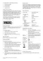
For example, to select a device address of 007, set SW1-1,
SW1-2, and SW1-3 to the ON position and the remaining
switch segments to the OFF position.
ON
1
2
3
4
5
6 7
SW1
1 2 4 8 16 32 64
Installing the backbox
The ZP787-3 is designed for surface mounting only. The unit is
comprised of a front housing and a backbox, as shown in
Figure 3.
To install the backbox:
1. Install the backbox using the screws provided.
2. Bring the field wiring into the backbox.
3. Use the plugs provided to cover unused holes in the
backbox.
Wiring the ZP787-3
Make the wiring connections shown in Figure 2.
Installing the ZP787-3
To install the front housing:
1. Slide the front housing onto the backbox, and then press
to snap them together as shown in Figure 3.
2. For additional security, the front housing can be secured
at the top and bottom using the four screws provided.
3. Test the MCP for proper operation using the test key
shown in Figure 5, item 1.
To remove the front housing:
1. If the front housing is secured to the backbox using
screws, remove the four screws (two at the top and two at
the bottom).
2. Insert a screwdriver into the slot as shown in Figure 4, and
then twist the screwdriver to separate the housing from the
backbox.
Maintenance
Figure 5, item 1 illustrates how to perform a test and reset for
the device. Use the supplied test key to perform routine testing
without breaking the glass element. Insert the key to simulate
breaking the glass element; remove the key to reset the call
point automatically. Figure 5, item 2 shows how to replace the
glass or resettable element.
Specifications
Operating voltage
19.5 to 20.5 VDC (pulsed
addressed line)
Current consumption
Standby
Alarm
0.400 mA
0.450 mA
Addressing method
Seven segment DIP switch
Mounting
Surface
Wiring
Two-core loop
Construction
Material
Colour
Weight
Dimensions (H x W x D)
Moulded ABS
Red
187 g
97.5 × 93 × 27.5 mm
Operating environment
Temperature
Storage temperature
Relative humidity
−25°C to +70°C
−20 to +70°C
10 to 95% noncondensing
Regulatory information
Manufacturer
KAC Alarm Company Limited
KAC House, Thornhill Road, North Moons Moat,
Redditch, B98 9ND, UK
EU authorized manufacturing representative:
UTC Fire & Security B.V.
Kelvinstraat 7, 6003 DH Weert, The Netherlands
Year of
manufacture
The first two digits of the product serial number
(located on the product identification label) are
the year of manufacture.
Product type
Type A: for outdoor use
EN 60529 rating
IP67
Certification
Certification body
0832
CPD certificate
0832-CPD-1398
EN 54
EN 54-11
2002/96/EC (WEEE directive): Products marked
with this symbol cannot be disposed of as
unsorted municipal waste in the European Union.
For proper recycling, return this product to your
local supplier upon the purchase of equivalent
new equipment, or dispose of it at designated
collection points. For more information see:
www.recyclethis.info.
Contact information
For contact information, see www.utcfireandsecurity.com.


