


997-532-000-1, Issue 1
March 2006
8
EN54 & ISO 7240 2-8 Zone Conventional Fire Panel - Installation & Configuration Manual
2.5
Installation Preparation
This section describes making the panel ready for
installation.
2.5.1
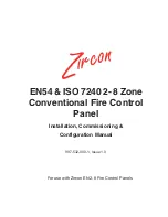
Removing the Cover
Remove the front cover as follows:
Use the supplied 4mm hexagonal socket wrench to release
the two recessed, socket-headed screws located in position
‘A’ - the screws are captive and do not need to be removed
from the cover moulding. Once the screws have disengaged
the back box, remove the cover as follows:
i
Gently pull the bottom edge of the cover clear of the
back box.
ii
Carefully lift the top edge of the cover up and away
from the back box to disengage the locating lugs.
iii Store the cover safely until required for re-fitting.
2.5.2
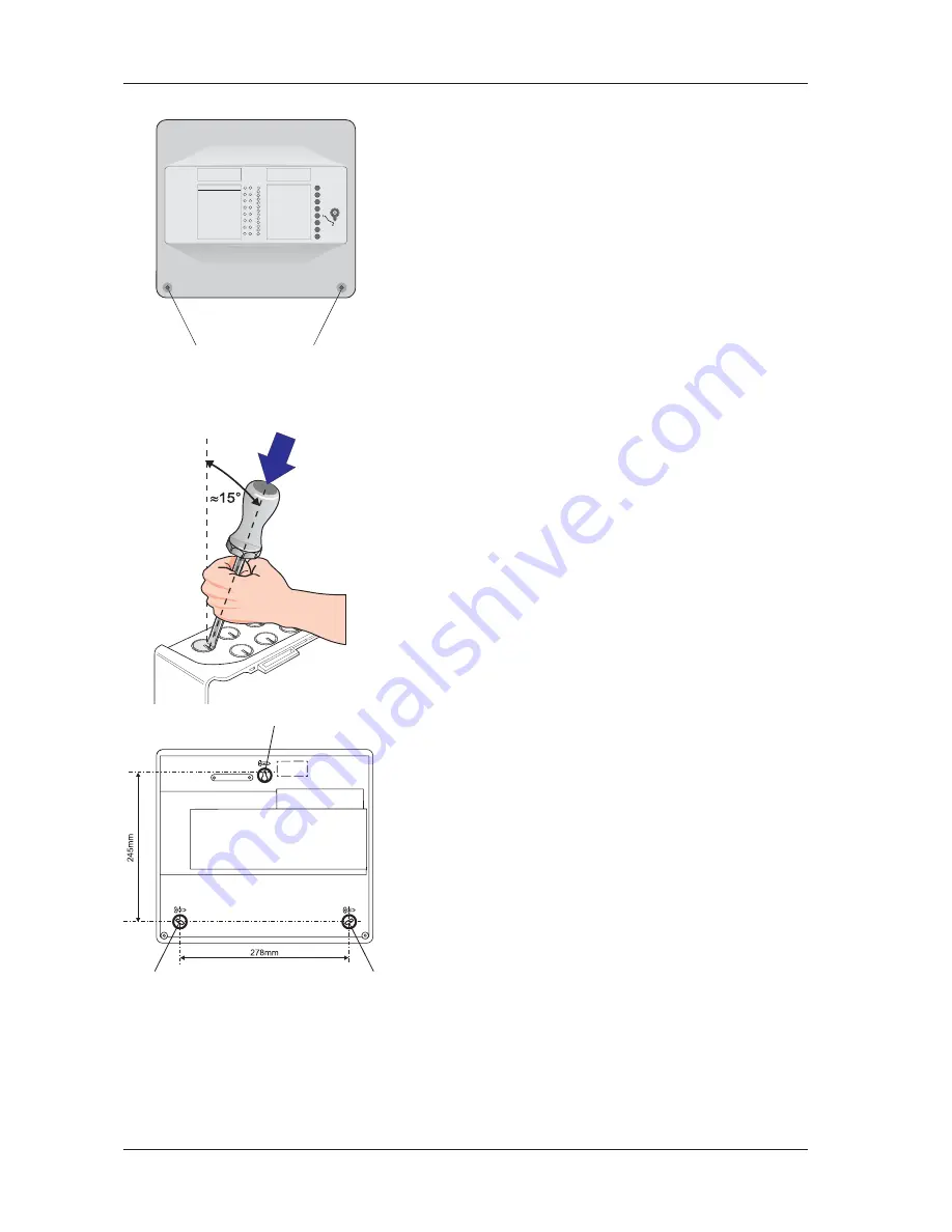
Back Box Fixing
The back box must be fixed to the wall with screws at three
fixing locations (see drawing) following the procedure
described below.
Wall Flatness
To prevent distortion, the back box must be installed on the
wall as flat as possible, i.e. with a maximum flatness
deviation between any two points of 3mm. Where the wall
is out of tolerance, use appropriate packing pieces when
installing the back box to meet the above requirements.
Failure to comply with this requirement may result in
the misalignment and consequent difficulty in fitting
the front cover or malfunction of control pushbuttons.
When a suitable location has been found for installing the
control panel, proceed as described below:
1
Prepare apertures (20mm knockouts) required for
cable access as follows:
With the cover removed position the back box so the
interior is towards you. Using a No. 5, slot-ended
screwdriver, position its end in the recess (A) of the
20mm knockout and incline the screwdriver towards you
at about 15° from the vertical (see illustration at left).
Support the screwdriver as illustrated to minimize
penetration of the back box. While in this position use
something suitable, such as a mallet, to strike the top of
the screwdriver to achieve a clean break of the knockout.
2
Hold the back box assembly in the required position
against the wall and mark the position of the keyhole (A).
3
Drill and plug the wall to take size 4 to 5mm screws.
4
With the panel supported by the top screw, and
ensuring that it is level, mark the other two screw
positions (B). Drill holes and plug.
5
Screw the panel back box to the wall using all three
fixing holes and 4 to 5mm steel, flat-underside-headed
screws.
DO NOT use countersunk-headed screws
.
Use washers with 4mm-sized screws.
A
A
Overrall Dimensions of panel in
millimetres:
318(h) x 355.5(w) x 96(d).
(Distance between fixing holes marked
on rear face of back box).
A
B
B
Summary of Contents for EN54
Page 41: ......


