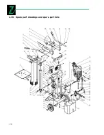
Zipper Mowers ZI-HS7 Operation Manual Download Page 25


25 


Pos.


Name 

Pcs. 

42 

Ajustable lever 

43 

switch 

44 

Screw M4x60 

45 

Motor 

46 

Bolt M10x30 

10 

47 

Oil coming spigot for pump     

48 

Pump    

49 

Hose Hoop 

50 

Suction hose 

51 

Spring washer  8 

52 

Inner hexangular screw M8x85 

53 

Oil returning hose 

54 

Oil returnning spigot for valve 

55 

Washer groupware 20 

56 

Hollow bolt M20x1.5 

57 

Inner hexangular screw M8x35 

58 

High pressure oil pipe 3 

59 

Valve 

60 

Pipe connector for valve 

61 

Oil going pipe spigot for pump 

62 

High pressure oil pipe 2 

63 

High pressure oil pipe 1 

64 

Three passage nut cap M20 

65 

Bolt M6x30 

66 

Locknut M6 

67 

Oleaginous cover 

68 

O-ring 25x3.55 

69 

Washer groupware 16 

70 

Bolt M16x1.5x25 

71 

Snap washer  16 

72 

wheel 

73 

Wheel shaft 

74 

Machine shelf  

75 

Lock handle 

76 

Snap Washer 20  

77 

Bolt M10X35   

78 

Cylinder   

79 

Down slip plank 

80 

Knife rest pipe 

81 

Pump cover 

Pos.


Name


Pcs.


Worktable 

Circulate stem 

Armguard cover  22 

Manipulative handle 

Right log clamp 

Right armguard hold assembly 

Star model knob 

Left log clamp 

Left armguard hold assembly 

10 

Locknut M8 

11 

Washer 8 

12 

Armguard handle pin 

13 

Thin nut M8 

14 

Bolt M8x40 

15 

Clip 

16 

Adjustable plank 

17 

Adjustable lever connector 

18 

handle jam 

19 

Four star knob 

20 

Tense pole guider 

21 

Nut cap M8 

22 

Tense pole 

23 

Short shaft 

24 

Snap washer -shaft 22 

25 

Up slip plank 4 

26 

Slip plank adjuster 2 

27 

Snap washer  6 

12 

28 

Gasket  6 

10 

29 

Inner hexangular screw M6x12 

30 

Inner hexangular screw M6x16 

31 

Snap washer -shaft  19 

32 

Long shaft 

33 

Armguard hold limitative plank 

34 

Locknut M4 

35 

Locknut M10 

10 

36 

washer  10 

44 

37 

Slip plank adjuster 1 

38 

Up slip plank 2 

39 

Up slip plank 1 

40 

Up slip plank 3 

41 

Thin nut M16 

Summary of Contents for ZI-HS7

Page 1: ...ípač EN Operation Manual Log splitter ZI HS7 EAN 912003923808 1 CZ Před použitím si přečtěte návod k použití a dodržujte bezpečnostní pokyny EN Read the operation manual carefully before first use 06 10 2011 revize 01 CZ EN ...

Page 2: ...zdraví EN READ THE MANUAL Read the user and maintenance manual care fully and get familiar with the controls n order to use the machine correct ly and to avoid injuries and machine defects CZ CE SHODNÉ Tento výrobek odpovídá směrnicím EU EN CE Conformal This product complies with the EC directives CZ OCHRANNÉ PROSTŘEDKY Používejte ochranu sluchu ochranné brýle a bezpečnostní obuv EN PROTECTIVE CLO...

Page 3: ...3 Fig 1 Fig 1 1 ...

Page 4: ...4 Fig 1 2 Fig 1 3 ...

Page 5: ...5 Fig 8 ...

Page 6: ...010 Tato dokumentace je chráněna autorským právem Všechna práva vyhrazena Zvláště nedovolený tisk překlady použití fotografií a vyobrazení budou trestně stíhány soudním místem je Wels Adresa zákaznického servisu Z I P P E R MASCHINEN GmbH Gewerbepark 8 A 4707 Schlüsslberg Tel 0043 0 7248 61116 700 Fax 0043 0 7248 61116 720 info zipper maschinen at 1 1 Přehled prvků stroje Fig 1 1 Transportní rukoj...

Page 7: ... ploše Pokud používáte stroj na louce dbejte na to aby byla tráva řádně posekaná 7 Zajistěte si při štípání jistý postoj Zajistěte aby štípač měl pevný podklad a nehrozí jeho pře vrácení To by mohlo vést k těžkým zraněním 8 Nedotýkejte se štípacího klínu abyste zamezili zranění třískami 9 Zabezpečte aby se nepřibližovali nepovolané osoby Při práci se žádné nepovolané osoby nebo zvířata nesmí přibl...

Page 8: ...i Stroj provozujte v prostorech nepřístupných dětem Také ostatní nepovolané osoby nesmí mít ke stroji přístup 1 5 Správné použití Stroj odpovídá platným směrnicím EU Špalky se smí štípat pouze po letech Je nutné dodr žovat všechny pracovní a bezpečnostní předpisy Je nutné dodržovat I všeobecné zásady předcházení úra zům Jakékoliv změny na štípači mají za následek ztrátu záruky Pro tento štípač se ...

Page 9: ...závěr olejové nádrže pevně dotažen 1 11 Uvedení do provozu Stroj musí být umístěn tak aby nedošlo k jeho převrácení Zabezpečte dostatek místa kolem stroje Před zahájením práce musí být všechny kryty a bezpečnostní prvky namontovány Zkontrolujte dotažení všech šroubů čepů a hydraulických vedení Dbejte na správnou hladinu hydraulického oleje Před použi tím se seznamte s bezpečnostními a ovládacími p...

Page 10: ... štípací klín k pohybu směrem dolů Štípací klín se musí asi 5 cm nad stolem zastavit b Pokud jednu páku uvolníte štípací klin se zastaví c Pokud uvolníte obě páky klín se vrátí zpět do horní polohy d Neuvolňujte štípací páky bezdůvodně v průběhu štípání Může tím dojít ke změně otáčení motoru 7 K nastavení výšky štípacího klínu postupujte následovně Fig 7 a Nastavte štípací klín do zvolené polohy 5...

Page 11: ...stranění ne čistot z větráku motoru 4 Namažte běžným strojním olejem všech ny pohyblivé součástky Výměny hydraulického oleje Olejová nádrž je z výroby naplněna kvalitním hydraulickým olejem třídy 20 Starý olej likvidujte v soula du s platnými předpisy V žádném případě olej nevylévejte do kanalizace půdy nebo vody Hydraulický systém je je uzavřený složený z nádrže čerpadla a regulačního ventilu Níz...

Page 12: ...é pořadí fází 2 1 Změňte pořadí fází šroubovákem v zástrčce 2 2 Změňte pořadí fází šroubovákem v zástrčce 3 Motor se točí klín se nepohybuje 3 1 Ventil není dosta tečně otevřen ovláda cími pákami 3 1 Dotáhněte ovládací páky 3 2 Nízký stav oleje 3 2 Doplňte olej 4 Štípač pracuje ale s netypickým zvukem a vibracemi 4 1 Nízký stav oleje 4 1 Doplňte olej 1 15 Likvidace Nelikvidujte váš stroj ZI HS7 do...

Page 13: ...13 1 16 Výkres a seznam náhradních dílů ...

Page 14: ...rrgriff 6 76 Ausrichtscheibe 20 2 77 Bolzen M10X35 6 78 Zylinder 1 79 Unteres Rutschbrett 4 80 Messerrohr 1 81 Pumpenabdeckung 1 Pos Name Pcs 1 Arbeitstisch 1 2 Drehscheibe 2 3 Armschutz Abdeckung 4 4 Handgriff 2 5 Rechte Spaltklemme 1 6 Rechter Armschutz 1 7 Sternrad 2 8 Linke Spaltklemme 1 9 Linker Armschutz 1 10 Sicherungsmutter M8 2 11 Scheibe 8 12 Stift für Armschutz 2 13 Dünne Mutter M8 2 14...

Page 15: ...pyright law all rights reserved Especially the reprinting as well as the translation and depiction of pictures will be prosecuted by law Court of jurisdiction is WELS Austria Customer Support Z I P P E R MASCHINEN GmbH Gewerbepark 8 A 4707 Schlüsslberg Tel 0043 0 7248 61116 700 Fax 0043 0 7248 61116 720 info zipper maschinen at 2 1 COMPONENTS Fig 1 1 Transport handle 2 Stroke adjusting rod 3 Split...

Page 16: ...ge of 16 years may only work on this machine under supervision 4 Never wear any jewellery rings necklaces watches etc or wide clothes such as oversized overalls gloves or shoes as these could be caught by moving parts Specific protective clothing such as safety shoes and special gloves are mandatory Always wear a hair net if you have longer or long hair 5 Always wear safety goggles Bear in mind th...

Page 17: ... for example or if you want to split a hard log This would result in quick overheating of the pressurized oil causing consequential damage to the machine It is advisable to turn the log 90 and to try to split it at this position If it is still impossible to split such log please dispose of it instead of subjecting it to any further splitting process to avoid damage to the machine 18 Do not press t...

Page 18: ...damage resulting therefrom and the risk of it shall solely be borne by the user 2 6 Residual Risks Even proper usage can still involve the following residual risks Injuries to your fingers and hands caused by the splitting tool Injuries by workpieces and parts coming off as a result of improper holding and guiding Injuries by contact with live parts when electric components are opened or defective...

Page 19: ... in the sketch below Then insert the lever and make sure that it has reached its intended end position C Now latch the lever by lock B and spring A Perform the same procedure for the other lever 2 You can set three different table positions to be able to split logs of various lengths Insert the ta ble into one of the three fixtures E provided for this purpose and turn hooks D by 90 lock it on eith...

Page 20: ...iar with its controls and safety elements and with how they work Make sure that the data indicated on the type label conform with your mains data before you connect your log splitter Size of Logs Fig 3 Choose your workplace in consideration of your safety regulations Keep your logs to be split ready to hand Remove the split logs from the work ing area Before you split your logs sort out those logs...

Page 21: ... come to a standstill some 5 cm above the topmost table position b If you release one of the two levers the splitting blade will stop at its current position c Releasing both levers will induce the splitting blade to automatically return to the top 7 To set the splitting blade follow the steps described below Fig 7 a Bring the splitting blade into the desired position The topmost position of the s...

Page 22: ...ng agents solvents or pointed objects 7 Use a soft brush to remove dust deposits from the motor ventilation slots and from moving parts at regular intervals 8 Apply some oil to all moving parts at regular intervals Hydraulic Oil Change IMPORTANT The oil tank is factory filled with high grade viscosity class 20 hydraulic oil Take waste oil to a public receiving depot or observe the relevant disposa...

Page 23: ... wall socket 1 1 Check fuse box 1 2 Extension cable defective 1 2 Unplug check and use new one if necessary 1 3 Wrong supply 400 V three phase current 1 3 5 pole plug with 1 5 mm diameter 1 4 Switch defective 1 4 Have it checked by electrician 6 Wrong motor di rection 2 1 Wrong polarity 2 1 Change polarity using a screwdriver electrician 2 2 Change polarity electrician 7 Splitter not movIng althou...

Page 24: ...24 2 16 Spare part drawings and spare part lists ...

Page 25: ...er 20 2 77 Bolt M10X35 6 78 Cylinder 1 79 Down slip plank 4 80 Knife rest pipe 1 81 Pump cover 1 Pos Name Pcs 1 Worktable 1 2 Circulate stem 2 3 Armguard cover 22 4 4 Manipulative handle 2 5 Right log clamp 1 6 Right armguard hold assembly 1 7 Star model knob 2 8 Left log clamp 1 9 Left armguard hold assembly 1 10 Locknut M8 2 11 Washer 8 8 12 Armguard handle pin 2 13 Thin nut M8 2 14 Bolt M8x40 2...

Page 26: ...ng date 26 01 2010 Ausstellungsbehörden issuing authorities TÜV Rheinland Tillystraße 2 90431 Nürnberg Germany Hiermit erklären wir dass die oben genannte Maschine den maßgeblichen Anforderungen des deutschen Produkt sicherheitsgesetzes entspricht Diese Erklärung verliert ihre Gültigkeit wenn Veränderungen an der Maschine vorgenommen werden die nicht ausdrücklich schriftlich im Vorfeld mit uns abg...

Page 27: ...27 ...

Reviews: