background image


21 


2


EN 


USER MANUAL  


Dear Customer! 

This  manual  contains  important  information  and 
advice  for  the  correct  and  safe  use  and  mainte-
nance of the ZIPPER garden maintenance set ZI-
GPS182.  The  manual  is  part  of  the  machine  and 
may not be stored separately. Read it profoundly 
before  first  use  of  the  machine  and  keep  it  for 
later  reference.  When  the  machine  is  handed  to 
other persons always put the manual to the ma-
chine.  


Please follow the security instructions! 

Due  to  continuous  development  of  our  products 
illustrations, pictures might differ slightly.  


Attention! 

Technical changes reserved! 


Copyright 

© 2010 
This  manual  is  protected  by  copyright  law  –  all 
rights  reserved.  Especially  the  reprinting  as  well 
as the translation and depiction of pictures will be 
prosecuted by law. Court of jurisdiction is WELS, 
Austria.  


Customer Support 


Z.I.P.P.E.R MASCHINEN GmbH 

Gewerbepark 8 
A-4707 Schlüsslberg 

Tel 0043 (0) 7248 61116 - 700 
Fax 0043 (0) 7248 61116 – 720 
[email protected] 


2.1


Components (Fig. A) 

Engine 

Extension pole 

Hedge trimmer 

Twig saw 

Brush cutter 

Trimmer 

Scythe blade 

Safety cover 

Angle adjustment hedge trimmer 

10 

Belt 

11 

Pole with control panel 

2.2


Technical Details 

Engine type 

2-stroke engine 

Displacement 

52 cm³ 

Engine power 

1,82 kW 

Maximum engine speed 

9000 rpm 

Idle speed 

2800 rpm 

Starter 

Reverse starter 

Ignition 

CDI 

Fuel capacity 

1,1 Litres 

Ratio fuel : oil 

40 :1 

Weight (net/gross) 

14,5 / 15,5 kg 

Trimmer:

 2-thread head 

Maximum cutting width 

455 mm 

Thread length 

2 m 

Thread thickness 

Ø2,4 mm 

Leaf scythe:

 3-tooth blade 

Blade dimensions 

Ø255xØ25,4x1,5 

Twig saw: 

Carlton sword 

Length 

1500 mm 

Sword length 

25,4 cm 

Hedge trimmer:

 180° adjustable 

Maximum cutting length 

400 mm 

Technical changes reserved. 

2.3


Included in delivery 

Unpack  the  ZIPPER  garden  maintenance  set  ZI-
GPS182 and check the machine for any transport 
damage and for completeness of delivery. 


Summary of Contents for ZI-GPS182

Page 1: ...npflegeset EN Operation Manual Garden maintenance set ZI GPS182 EAN 9120039239163 DE Bedienungsanleitung und Sicherheits hinweise vor Erstinbetriebnahme lesen und beachten EN Read the operation manual...

Page 2: ...em lyi s r l seket s hal los vesz lyt vonhat maga ut n CZ POZOR Dbejte na bezpe nostn symboly Nedodr ovn p edpis a pokyn pro pou it stroje m e v st ke kod m a t k m zran n m DE ANLEITUNG LESEN Lesen S...

Page 3: ...fumes Engine parts and muffler become hot during operation ES RIESGO DE QUEMADURAS Vapores calientes Las partes del motor y el silenciador se calientan durante la operaci n FR RISQUE DE BRULURE Vapeu...

Page 4: ...l This product complies with the EC directives ES CE CONFORME Este producto cumple con las Directivas CE FR CE CONFORME Ce produit est conforme aux Directives CE HU CE KONFORM Ez a term k megfelel az...

Page 5: ...5...

Page 6: ...6...

Page 7: ...7...

Page 8: ...8...

Page 9: ...9 Fig Y Fig Z Fig a Fig b Fig c Fig d 32 33 34 35 36 38 37 39...

Page 10: ...ist Bestandteil der Maschine und darf nicht entfernt werden Bewahren Sie sie f r sp tere Zwecke auf und legen Sie diese Anlei tung der Maschine bei wenn sie an Dritte weiter gegeben wird Bitte beacht...

Page 11: ...ale Schnittbreite 455 mm Fadenl nge 2 m Fadenst rke 2 4 mm Sensenblatt 3 Zahnblatt Blattabmessungen 255x 25 4x1 5 Asts ge Carlton Schwert L nge 1500 mm Schwertl nge 25 4 cm Heckenschere 180 verstellba...

Page 12: ...ge der Maschine Nach dem Be trieb muss die Maschine ausk hlen Sonst besteht akute Verbrennungsgefahr 1 5 Montage HINWEIS Achten Sie beim Zusammenbau darauf dass bei vorhandenen Verzahnungen diese ine...

Page 13: ...l regulieren Verwenden Sie dazu den Gashebel der in Fig L dargestellt ist Dr cken Sie zuerst den Verriegelungshe bel 18 Nun kann der Gashebel 19 bet tigt wer den 1 7 Bedienung Beim Betrieb der Maschin...

Page 14: ...ng und Wartungs plan Kontrollen zur Instandhaltung der Maschine Lockere oder ver lorene Schrauben T glich vor Inbetrieb nahme Besch digung ir gendwelchen Tei les T glich vor Inbetrieb nahme Maschine s...

Page 15: ...igersinn um sie zu lockern 1 8 7 Wechseln der Kette L sen Sie die Mutter 32 und entfernen Sie die Abdeckung 33 Fig Y Lockern Sie nun die Kette Entfernen Sie die Kette Achten Sie beim Einbau darauf das...

Page 16: ...n gleichwertiges Ger t kaufen ist die ser in bestimmten L ndern verpflichtet Ihre al te Maschine fachgerecht zu entsorgen 1 9 Ersatzteilbestellung Mit Originalteilen von Zipper verwenden Sie Er satzte...

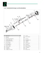
Page 17: ...kranz 1 7 Schraube M6x20 4 8 Gummiabdeckung 1 9 Schraube M5x25 3 10 Schraube M5x12 1 11 Fixierplatte I 1 12 Fixierplatte II 1 13 Handb gel mit Schalter 1 14 Gurtring 1 15 Schraube M5x25 1 16 1 17 Mutt...

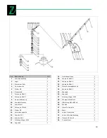
Page 18: ...bindungsplatte 1 15 Scheibe 10 1 16 Scheibe 26 1 17 Rillenkugellager 6000 3 18 Kegelrad 1 19 Getriebegeh use 1 20 Schraube M5x35 1 21 Schraube M6x18 1 22 Schraube M6x12 1 23 Obere Schutzabdeckung 1 24...

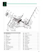
Page 19: ...ilagscheibe 6 5x 13x1 5 14 Wellenscheibe 6 5x 13x1 1 15 Getriebegeh use 1 16 Getrieberad 1 17 Schraube M5x16 2 18 O Ring 1 19 Beilagscheibe 10x 16x2 2 20 Nadellager 2 21 Doppelkegelrad 1 22 Getriebege...

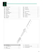
Page 20: ...bdeckung 1 43 Exzenterrad 1 44 Getriebe 1 45 Fixierplatte 1 46 Nockenwelle 1 47 Getriebewelle 1 48 2 49 Schraube M6x18 2 50 Griff 1 51 Ausl sefeder 1 52 Ausl severriegelung 1 53 Einsteller 1 54 Schrau...

Page 21: ...R MASCHINEN GmbH Gewerbepark 8 A 4707 Schl sslberg Tel 0043 0 7248 61116 700 Fax 0043 0 7248 61116 720 info zipper maschinen at 2 1 Components Fig A 1 Engine 2 Extension pole 3 Hedge trimmer 4 Twig sa...

Page 22: ...e getting very hot Use proper safety clothing and devices when operating the machine safety gloves safety goggles ear protectors safety shoes The machine may only be operated out doors If there are so...

Page 23: ...opping Turn the ignition 16 to the position O Fig H Wait till the engine stands still and all components are cold again 2 6 4 Regulating the engine speed For this you have to use the throttle han dle...

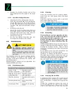
Page 24: ...aning Clean the machine and the working attach ment from soil dust grass chips and small twigs etc Clean the machine housing with a wet cloth and a mild cleaning solution Put on all coatless flats a t...

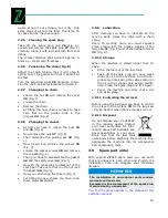
Page 25: ...teps backwards 2 8 9 Lubrication After cleaning you have to lubricate all the moving parts Spray the chain with a chain spray Every 15 working hours you must squeeze some grease into the grease nipple...

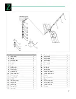
Page 26: ...tch rim 1 7 Screw M6x20 4 8 Rubber cover 1 9 Screw M5x25 3 10 Screw M5x12 1 11 Fixing plate I 1 12 Fixing plate II 1 13 Hand bar with switch 1 14 Belt ring 1 15 Screw M5x25 1 16 1 17 Nut M5 5 18 Rubbe...

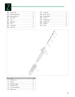
Page 27: ...ut M5 5 14 Connecting plate 1 15 Washer 10 1 16 Washer 26 1 17 Bearing 6000 3 18 Cone gear 1 19 Gear housing 1 20 Screw M5x35 1 21 Screw M6x18 1 22 Screw M6x12 1 23 Upper safety cover 1 24 Screw M5x10...

Page 28: ...ave washer 6 5x 13x1 1 15 Gear housing 1 16 Gear wheel 1 17 Screw M5x16 2 18 O Ring 1 19 Flat washer 10x 16x2 2 20 Needle bearing 2 21 Double cone gear 1 22 Gear housing 1 23 Flange M 2 24 Connecting...

Page 29: ...r 1 44 Gear 1 45 Fixing plate 1 46 Cam shaft 1 47 Gear shaft 1 48 Butter mouth 2 49 Screw M6x18 2 50 Handle 1 51 Trigger spring 1 52 Trigger lock 1 53 Adjuster 1 54 Screw 2 Pos Name Pcs 1 Rubber cover...

Page 30: ...rnberg GERMANY Ausstellungsdatum issuing date s 13 04 2012 Hiermit erkl ren wir dass die oben genannten Maschinen den f r eine Zertifizierung ma geblichen Anforderungen oben genannter Richtlinien ent...

Reviews: