background image

OPERATION 

ZIPPER MASCHINEN GmbH     www.Zipper-Maschinen.at



41   

ZI-HS13E / ZI-HS18EZ / ZI-HS25Z / ZI-HS25EZ 


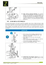
Check the  rotation  direction of the motor. Switch on the 
motor (position: O

N

). After switching on, the splitting arm 

automatically moves to the highest position. 
If  the  splitting  arm  is  already  in  the  highest  position, 
activate the splitting mechanism by moving the two control 
levers  downwards  and  the  splitting  arm  will  move 
downwards. 

 
If  the  splitting  arm  does  not  start  moving  after  starting  the  motor,  switch  off  the  motor 
immediately (position: O

FF

). Then reverse the polarity of the motor using a screwdriver (phase 

inverter inside the plug - see picture on the left). 

16.2


Operating 

16.2.1


Splitting lever 

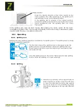
Splitting force and splitting speed are controlled by the splitting lever. The splitting lever is simply 
raised or lowered for operation. 


The first half stroke of the splitting lever is idle speed; press the 
splitting lever to the half stroke for maximum splitting force at 
slower speed to split the log at the beginning or particularly hard 
and seasoned logs. 


Press the splitting lever to the end for faster speed at less splitting 
force to finish the splitting or to split usual logs. 


16.2.2


Splitting 


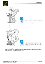
1.


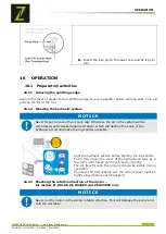
Place the log vertically on the support table, so 
that it lies flat on its face. Press the left lever 
to  lower  the  extended  log  fixing  claw  against 
the  log  to  secure  it.  The  extended  log  fixing 
claw can be adjusted to fit logs with different 
heights. 

Phase inverter 

Summary of Contents for ZI-HS16E

Page 1: ...8 2018 Revision 00 PLC DE EN Originalfassung DE BETRIEBSANLEITUNG HOLZSPALTER Übersetzung Translation EN USER MANUAL LOG SPLITTERS ACHTUNG Öl kontrollieren ATTENTION Check Oil ZI HS30EZ ZI HS30Z ZI HS16E ZI HS22EZ ...

Page 2: ...ntlüften 22 8 1 3 Drehrichtung des Motors überprüfen nur für die Modelle ZI HS16E ZI HS22EZ ZI HS30EZ 22 8 2 Bedienung 23 8 2 1 Spalthebel 23 8 2 1 Spaltvorgang 23 8 2 2 Eingeklemmtes Holz entfernen 24 9 WARTUNG 25 9 1 Wartungsplan 25 9 2 Hydrauliköl wechseln 25 9 3 Spaltkeil schärfen 26 9 4 Getriebe Schmierung nur für Modelle ZI HS22EZ und ZI HS30 E Z 26 10 ENTSORGUNG 27 11 FEHLERBEHEBUNG 27 12 P...

Page 3: ...ZI HS22EZ and ZI HS30 E Z only 44 18 DISPOSAL 45 19 TROUBLESHOOTING 45 20 SCHALTPLAN WIRING DIAGRAM 46 21 HYDRAULIKSCHEMA HYDRAULIC SCHEME 46 21 1 ZI HS16E ZI HS30Z 46 21 2 ZI HS22EZ ZI HS30EZ 46 22 ERSATZTEILE SPARE PARTS 47 22 1 Ersatzteilbestellung Spare Parts Order 47 22 2 Explosionszeichnungen Explosion Drawings 48 22 2 1 ZI HS16E 48 22 2 2 ZI HS22EZ ZI HS30 E Z 51 23 EG KONFORMITÄTSERKLÄRUNG...

Page 4: ...of your machine in order to be able to operate and maintain it properly and thus prevent damage to man and machine DE Halten Sie Ihren Arbeitsplatz aufgeräumt Unordnung kann zu Unfällen führen EN Keep your workspace tidy Untidiness may result in accidents DE Es ist verboten Schutz oder Sicherheitseinrichtungen zu entfernen oder zu manipulieren EN Do not remove or tamper with any protection or safe...

Page 5: ...y repiar maintenance or cleaning always disconnect device from the mains DE Vermeiden Sie Verletzungen durch den bewegenden Spaltkeil EN Avoid injury from the movement of the splitting blade DE Kinder und unbefugte Personen vom Arbeitsbereich fern halten EN Keep children and bystanders away from the work area DE Persönliche Schutzausrüstung tragen EN Wear personal protective equipment ...

Page 6: ...lte Haken retaining hook 5 Räder wheels 6 Radachse wheel shaft 7 Stützrad support wheel 8 Bedienungsanleitung operator s manual 9 Beutel mit Kleinteilen inklusive hardware bag including 1 Holzspalter Rahmen Antriebseinheit log splitter frame power unit 2 Schutzarm guard arm 3 Stammheber log lift 4 Rückhalte Haken retaining hook 5 Zapfwellen Abdeckung PTO cover 6 Stützrad support wheel 7 Bedienungs...

Page 7: ... weight 258 kg 320 kg 373 kg 333 kg ELEKTRISCHE ANFORDERUNGEN Mit dem 3 Phasen 400 Volt 50Hz Motor sollte der Brennholz Spalter an ein Standardstromnetz von 400 V 10 50 Hz 1 Hz angeschlossen werden Die elektrische Versorgung muss mit Schutzeinrichtungen gegen Unterspannung Überspannung Überstrom und mit einer Fehlerstrom Schutzeinrichtung mit einem maximalen Nennfehlerstrom von 0 03 A ausgerüstet ...

Page 8: ...3 Motor motor 13 Steuerhandgriff 1 control handle 1 4 Pumpe 1 pump 1 14 Steuerhandgriff 2 control handle 2 5 Stützrad support wheel 15 Hubkette lift chain 6 Zapfwellenstummel PTO stub 16 Sicherungshaken retaining hook 7 Rad wheel 17 Stammheber log lift 8 Pumpe 2 pump 2 18 Spaltkeil splitting wedge 9 Basisgestell base frame 19 Gefederter Einfahrhebel spring loaded retract control lever 10 Schutzarm...

Page 9: ...ng aufmerksam durch Der sachgemäße Umgang wird Ihnen dadurch erleichtert Missverständnissen und etwaigen Schäden wird vorgebeugt Halten Sie sich an die Warn und Sicherheitshinweise Missachtung kann zu ernsten Verletzungen führen Durch die ständige Weiterentwicklung unserer Produkte können Abbildungen und Inhalte geringfügig abweichen Sollten Sie Fehler feststellen informieren Sie uns bitte Technis...

Page 10: ...hen Bedingungen Betreiben der Maschine außerhalb des vorgegebenen Leistungsbereiches Entfernen der an der Maschine angebrachten Sicherheitskennzeichnungen Verändern umgehen oder außer Kraft setzen der Sicherheitseinrichtungen der Maschine 5 1 Sicherheitshinweise Warnschilder und oder Aufkleber an der Maschine die unleserlich sind oder entfernt wurden sind umgehend zu erneuern Örtlich geltende Gese...

Page 11: ... Verlängerungskabel Trennen Sie das Gerät vor Reinigungs Wartungs oder Reparaturarbeiten stets von der Energie bzw Antriebsquelle und sichern sie es gegen unbeabsichtigtes Wiedereinschalten Verwenden Sie nur intaktes Werkzeug 5 2 Restrisiken Trotz bestimmungsmäßiger Verwendung bleiben bestimmte Restrisiken bestehen Bedingt durch Aufbau und Konstruktion der Maschine können Gefährdungssituationen au...

Page 12: ...eine Unterlegscheibe auf die Achse dann ein Rad gefolgt von einer weiteren Unterlegscheibe Sichern Sie das Rad mit einem Splint ab Wiederholen Sie den Vorgang auf der gegenüberliegenden Seite C Zylinder hochfahren Halten Sie die Stütze gegen den Keil und senken Sie beide Steuerhandgriffe ab um den Zylinder hochzufahren 1 Setzen Sie die L Bolzen ein um den Zylinder am Holzspalter zu befestigen 2 3 ...

Page 13: ...ütze D Schutzarm befestigen Richten Sie die Bohrung und den Sicherungsstift des Schutzarms an der Halterung aus Befestigen Sie den Schutzarm mit einer M10x40 Sechskantschraube zwei Unterlegscheiben und einer Mutter aus dem mitgelieferten Kleinteile Beutel E Sicherungshaken montieren Setzen Sie den Sicherungshaken auf den Rahmen und befestigen Sie ihn mit zwei M10x35 Sechskantschrauben und Muttern ...

Page 14: ...mheber befestigen Positionieren Sie den Stammheber innerhalb der Halterung und richten Sie die Löcher an den Bohrungen der Halterung aus Befestigen Sie den Stammheber mit einer Sechskantschraube M16x100 und Mutter 1 Hängen Sie die Hubkette in die Keilschlittenführung und in den Sicherungshaken ein 2 3 ...

Page 15: ... ZI HS18EZ ZI HS25Z ZI HS25EZ 6 2 ZI HS22EZ und ZI HS30 E Z A Aufnahmestifte befestigen Befestigen Sie die Aufnahmestifte an der Anhängevorrichtung B Zapfwellenabdeckung montieren Montieren Sie die Zapfwellenabdeckung Muffenschloss Staubschutzhülse Einhänge Schnalle ...

Page 16: ...e die Stütze gegen den Keil und senken Sie beide Steuerhandgriffe ab um den Zylinder hochzufahren 1 Setzen Sie die L Stifte ein um den Zylinder am Holzspalter zu befestigen 2 3 Sichern Sie die L Stifte in den Federnasen 4 Stütze entfernen Lassen Sie beide Steuerhebel los um den Spaltkeil zurückzuziehen Entfernen Sie die Stütze ...

Page 17: ...Mutter aus dem mitgelieferten Kleinteile Beutel E Sicherungshaken montieren Setzen Sie den Sicherungshaken auf den Rahmen und befestigen Sie ihn mit zwei M10x35 Sechskantschrauben und Muttern F Stammheber befestigen Positionieren Sie den Stammheber innerhalb der Halterung und richten Sie die Löcher an den Bohrungen der Halterung aus Befestigen Sie den Stammheber mit einer Sechskantschraube M16x100...

Page 18: ...Befestigen Sie das Stützrad mit Sicherungsstift und Gelenkbolzen siehe Bild links H Zum Arbeiten den Sicherungsstift in die obere Bohrung stecken Zum Transport Sicherungsstift in die untere Bohrung einsetzen Sicherungsstift Gelenkbolzen Obere Bohrung für Sicherungsstift Schwenkloch Untere Bohrung für Sicherungsstift ...

Page 19: ...en auf jeweils beiden Seiten der Hinterräder gegen abrollen 3 Entfernen Sie die selbstsichernde Kunststoffhülse des Holzspalters und hängen Sie sie an den Zapfwellenschutz 4 Schieben Sie die Unterlenker auf die Anschlussbolzen des Holzspalters und sichern Sie diese mit Sicherungsstiften 5 Positionieren Sie den Oberlenker innerhalb des Montagebügels und richten Sie ihn an den Befestigungsbohrungen ...

Page 20: ...Gelenkwelle Trennen Sie die Gelenkwelle von den Zapfwellenenden ab 5 Montieren Sie die selbstsichernde Schutzhülse 7 TRANSPORT 7 1 ZI HS16E Für den leichteren Transport verfügt der Holzspalter über zwei Rädern ein Stützrad und einen Transportgriff WARNUNG Bei Verwendung eines Krans zum Heben den Kranhaken ausschließlich an der vorgesehenen Hebestelle a befestigen siehe Abbildung links Niemals den ...

Page 21: ...tellen Sie sicher dass der Holzspalter hoch genug angehoben ist um Hindernissen während des Transports ausweichen zu können Transportieren Sie den Holzspalter niemals bei eingeschalteter Zapfwelle Berücksichtigen Sie in Fahrsituationen z B beim Wenden Parken und Überqueren von Kreuzungen die durch den Anbau bedingte Überlänge HINWEIS Bei Verwendung eines Krans zum Heben den Kranhaken ausschließlic...

Page 22: ...nnt was zur Folge hat dass die Dichtungen des Hydraulikkreislaufes zerstört werden und der Holzspalter nicht mehr benutzbar ist Entlüften Sie das Hydraulik System bevor Sie den Holzspalter starten Lockern Sie dazu den Deckel des Hydrauliköl Tanks um einige Umdrehungen bis die Luft sanft ein und ausströmen kann Der Luftstrom durch den Öl Tank sollte während des Betriebes erkennbar sein Um das Ausfl...

Page 23: ...2 Bedienung 8 2 1 Spalthebel Spaltkraft und Spaltgeschwindigkeit werden mit dem Spalthebel gesteuert Die Bedienung erfolgt durch einfaches Anheben oder Absenken des Spalthebels Für maximale Spaltkraft bei geringerer Geschwindigkeit wie sie zum Beispiel zu Beginn des Spaltvorgangs benötigt wird oder um besonders harte und abgelagerte Stämme zu spalten drücken Sie den Spalthebel auf den halben Hub D...

Page 24: ...ändig gespalten ist 3 Den Spaltkeil in die Ausgangsposition zurückbringen Betätigen Sie den federunterstützten Einfahrhebel um den Keil über die Höhe des zu spaltenden Holzes zurückzubringen 8 2 2 Eingeklemmtes Holz entfernen Versuchen Sie weder selbst noch mit Hilfe anderer Personen eingeklemmtes Holz mit bloßen Händen zu entfernen Bei Klemmen des Holzes Motor anhalten Danach Holzstück gegebenenf...

Page 25: ...bh in der Folge halb jährlich oder nach jeweils 250 bh Nach 25 bh in der Folge halb jährlich oder nach jeweils 250 bh bh Betriebsstunden 9 2 Hydrauliköl wechseln HINWEIS Überprüfen Sie den Ölstand regelmäßig Wechseln Sie das Hydrauliköl mindestens einmal jährlich vollständig Altöl immer richtig entsorgen und nie in den Hausmüll oder ins Abwasser schütten Das Hydrauliksystem des Holzspalters ist ei...

Page 26: ...h Holz zu spalten Überprüfen Sie den Öl Füllstand mittels Peilstab 9 3 Spaltkeil schärfen Der Holzspalter ist mit einem verstärkten Spaltkeil mit speziell behandelter Schneide ausgerüstet Nach langer Betriebszeit und wenn erforderlich ist der Keil mit einer feinen Feile zur Entfernung von Graten oder Kerben zu schärfen 9 4 Getriebe Schmierung nur für Modelle ZI HS22EZ und ZI HS30 E Z Das Getriebe ...

Page 27: ...den für Informationen bezüglich der ordnungsgemäßen Entsorgung 11 FEHLERBEHEBUNG PROBLEM MÖGLICHE URSACHE MÖGLICHE LÖSUNG Motor startet nicht Schalter steht auf AUS Aufsteckhülse ist nicht verbunden s Abschnitte 6 2 1 und 6 2 2 Schalter auf EIN stellen Aufsteckhülse verbinden Falsche Motor Drehrichtung Falscher Anschluss Umpolen mit einem Schraubendreher Elektriker Polarität umkehren Elektriker Ho...

Page 28: ...uctions carefully before use This facilitates proper handling and prevents misunderstandings and possible damage Follow the warnings and safety instructions Failure to do so may result in serious injury Due to the constant further development of our products illustrations and contents may differ slightly If you find any errors please inform us Subject to technical changes Copyright 2018 This docum...

Page 29: ...ng the machine outside the specified power range Remove the safety markings attached to the machine Modify circumvent or disable the safety devices of the machine 13 1 Safety instructions Warning signs and or stickers on the machine which are illegible or have been removed must be replaced immediately Local laws and regulations can determine the minimum age of the operator and restrict the use of ...

Page 30: ...se suitable extension cords Before cleaning maintenance or repair work always disconnect the device from the power or drive source and secure it against unintentional reconnection Only use intact tools 13 2 Residual risks Despite proper use certain residual risks remain Due to the design and construction of the machine hazardous situations may occur which are indicated as follows in these operatin...

Page 31: ... nuts to the splitter B Mounting the wheels Place a washer onto the axle then a wheel followed by another washer and secure with a cotter pin Repeat procedure for the other side C Expanding the wedge ram Keeping the support stand against the wedge lower both control handles to expand wedge ram 1 Insert the L pins to secure the cylinder to the splitter 2 Lock the L pins into the spring tabs 3 4 ...

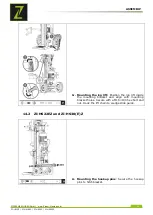
Page 32: ... to retract the wedge ram Remove the support stand E Mounting the guard arm Align the hole and locking pin of the guard arm with the mount bracket Secure the guard arm with a M10 40 hex bolts two washers and a nut from the hardware bag F Mounting the retaining hook Position the retaining hook onto the frame and secure with two M10 35 hex bolts and nuts ...

Page 33: ...25EZ G Mounting the log lift Position the log lift inside the mounting bracket and align with mounting bracket holes Secure with a M16 100 hex bolt and nut Hook the lift chain to wedge slide guide 14 2 ZI HS22EZ und ZI HS30 E Z A Mounting the hookup pins Secure the hookup pins to hitchbracket ...

Page 34: ...EZ B Attaching the PTO cover Attach the PTO cover with two M10 nuts to the splitter C Expanding the wedge ram Keeping the support stand against the wedge lower both control handles to expand wedge ram Insert the L pins to secure the cylinder to the splitter Lock the L pins into the spring tabs ...

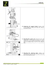
Page 35: ... to retract the wedge ram Remove the support stand E Mounting the guard arm Align the hole and locking pin of the guard arm with the mount bracket Secure the guard arm with a M10 40 hex bolts two washers and a nut from the hardware bag F Mounting the retaining hook Position the retaining hook onto the frame and secure with two M10 35 hex bolts and nuts ...

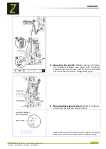
Page 36: ...lift inside the mounting bracket and align with mounting bracket holes Secure with a M16 100 hex bolt and nut Hook the lift chain to wedge slide guide H Mounting the support wheel Mount the support wheel with the lock pin and pivot bolt Insert the lock pin into the upper hole for working and insert it into the lower hole for transporting ...

Page 37: ...ear wheels on both sides in front and back with wedges or other appropriate objects 3 Remove the plastic self locking sleeve of the log splitter and hang it on the PTO shield 4 Slide the lower draft arms onto the splitter hookup pins and secure withlocking pins 5 Position the upper draft arm inside the mounting bracket and align with the mounting bracket holes Insert the hitch pin to secure the up...

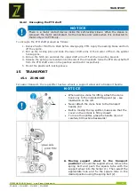
Page 38: ...d on both ends of the driveshaft Slide the PTO driveshaft off from the PTO shaft ends on the gearbox and tractor respectively 5 Mount the plastic self locking sleeve 15 TRANSPORT 15 1 ZI HS16E For easier transport the log splitter has two wheels a support wheel and a transport handle NOTICE When using a crane for lifting attach the crane hook only to the intended lifting point a see illustration o...

Page 39: ... the tractor and that the safety chains are in place Make sure that the splitter is raised high enough to avoid obstacles during transport Never transport the log splitter when the PTO shaft switched on In driving situations e g when turning parking or passing crossings take into account the excess length caused by the attached log splitter NOTICE When using a crane for lifting attach the crane ho...

Page 40: ...em will be compressed and released again and again which will destroy the seals of the hydraulic circuit and make the log splitter unusable Vent the hydraulic system before starting the log splitter To do this loosen the cover of the hydraulic oil tank by a few turns until the air can flow in and out gently The air flow through the oil tank should be visible during operation To prevent oil from le...

Page 41: ...lug see picture on the left 16 2 Operating 16 2 1 Splitting lever Splitting force and splitting speed are controlled by the splitting lever The splitting lever is simply raised or lowered for operation The first half stroke of the splitting lever is idle speed press the splitting lever to the half stroke for maximum splitting force at slower speed to split the log at the beginning or particularly ...

Page 42: ...stroke to split the log slowly first and then press it to the end until the log is completely split 3 Return the splitter wedge to the starting position Operate the spring loaded retract control lever to lift wedge above the height of log to be split 16 2 3 Free a jammed log Stack as you work This will provide a safer work area by keeping it uncluttered and avoid the danger of tripping or damaging...

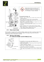
Page 43: ...ery 250 oh after 25 oh subsequently every six months or every 250 oh after 25 oh subsequently every six months or every 250 oh oh operating hours 17 2 Replacing Oil NOTICE Check the oil level regularly Change the hydraulic oil completely at least once a year Always dispose of used oil correctly and never throw it into household waste or sewage The hydraulic system of the log splitter is a closed s...

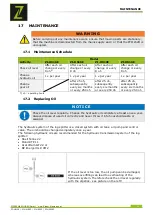
Page 44: ...ain After changing the oil actuate the wood splitter several times without actually splitting any wood Use a dipstick to check the oil level 17 3 Sharpening Wedge This log splitter is equipped with reinforced splitting wedge which blade is specially treated After long periods of operation and when required sharpen the wedge using a fine toothed file removing any burrs or flat spots on the edge 17 ...

Page 45: ...r Informationen bezüglich der ordnungsgemäßen Entsorgung 19 TROUBLESHOOTING PROBLEM PROBABLE CAUSE REMEDY SUGGESTED Motor does not start Switch is OFF Self locking sleeve is disconnected see chapters 14 2 1 and 14 2 2 Set switch to ON Connect self locking sleeve Incorrect motor rotation direction Incorrect connection Reverse polarity by an electrician Log Splitter does not work while motor running...

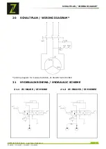
Page 46: ...NEN GmbH www Zipper Maschinen at 46 ZI HS13E ZI HS18EZ ZI HS25Z ZI HS25EZ 20 SCHALTPLAN WIRING DIAGRAM Wiring diagram for models ZI HS16E ZI HS22EZ ZI HS30EZ 21 HYDRAULIKSCHEMA HYDRAULIC SCHEME 21 1 ZI HS16E ZI HS30Z 21 2 ZI HS22EZ ZI HS30EZ ...

Page 47: ... sowie Bezeichnung an Um Missverständnissen vorzubeugen empfehlen wir mit der Ersatzteilbestellung eine Kopie der Ersatzteilzeichnung beizulegen auf der die benötigten Ersatzteile eindeutig markiert sind Bestelladresse sehen Sie unter Kundendienstadressen im Vorwort dieser Dokumentation With original ZIPPER spare parts you use parts that are attuned to each other shorten the installation time and ...

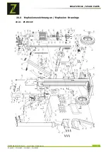
Page 48: ...ERSATZTEILE SPARE PARTS ZIPPER MASCHINEN GmbH www Zipper Maschinen at 48 ZI HS13E ZI HS18EZ ZI HS25Z ZI HS25EZ 22 2 Explosionszeichnungen Explosion Drawings 22 2 1 ZI HS16E ...

Page 49: ...ERSATZTEILE SPARE PARTS ZIPPER MASCHINEN GmbH www Zipper Maschinen at 49 ZI HS13E ZI HS18EZ ZI HS25Z ZI HS25EZ Teile Liste Parts List ZI HS16E ...

Page 50: ...ERSATZTEILE SPARE PARTS ZIPPER MASCHINEN GmbH www Zipper Maschinen at 50 ZI HS13E ZI HS18EZ ZI HS25Z ZI HS25EZ Teile Liste Parts List ZI HS16E Fortsetzung Sequel ...

Page 51: ...ERSATZTEILE SPARE PARTS ZIPPER MASCHINEN GmbH www Zipper Maschinen at 51 ZI HS13E ZI HS18EZ ZI HS25Z ZI HS25EZ 22 2 2 ZI HS22EZ ZI HS30 E Z ...

Page 52: ...TZTEILE SPARE PARTS ZIPPER MASCHINEN GmbH www Zipper Maschinen at 52 ZI HS13E ZI HS18EZ ZI HS25Z ZI HS25EZ Teile Liste Parts List ZI HS22EZ ZI HS30 E Z Parts with grey background are not in use for ZI HS30Z ...

Page 53: ...ARE PARTS ZIPPER MASCHINEN GmbH www Zipper Maschinen at 53 ZI HS13E ZI HS18EZ ZI HS25Z ZI HS25EZ Teile Liste Parts List ZI HS22EZ ZI HS30 E Z Fortsetzung Sequel Parts with grey background are not in use for ZI HS30Z ...

Page 54: ...N 609 1 2017 Hiermit erklären wir dass die oben genannten Maschinen aufgrund ihrer Bauart in der von uns in Verkehr gebrachten Version den grundlegenden Sicherheits und Gesundheitsanforderungen der angeführten EG Richtlinien entsprechen Diese Erklärung verliert ihre Gültigkeit wenn Veränderungen an der Maschine vorgenommen werden die nicht mit uns abgestimmt wurden Hereby we declare that the above...

Page 55: ...g von falschem Treibstoffen Frostschäden in Wasserbehältern Treibstoff über Winter im Benzintank des Gerätes c Ausgeschlossen sind Defekte an Verschleißteilen wie Kohlebürsten Fangsäcke Messer Walzen Schneideplatten Schneideeinrichtungen Führungen Kupplungen Dichtungen Laufräder Sageblätter Spaltkreuze Spaltkeile Spaltkeilverlängerungen Hydrauliköle Öl Luft u Benzinfilter Ketten Zündkerzen Gleitba...

Page 56: ... damages in water tanks leaving fuel in the tank during the winter etc c Defects on wear parts are excluded e g carbon brushes collection bags knives cylinders cutting blades clutches sealings wheels saw blades splitting crosses riving knives riving knife extensions hydraulic oils oil air fuel filters chains spark plugs sliding blocks etc d Also excluded are damages on the machine caused by incorr...

Page 57: ...he frame of a Quality Management policy Your opinion is essential for further product development and product choice Please let us know about your Impressions and suggestions for improvement experiences that may be useful for other users and for product design Experiences with malfunctions that occur in specific operation modes We would like to ask you to note down your experiences and observation...

Page 58: ...PRODUKTBEOBACHTUNG PRODUCT MONITORING ZIPPER MASCHINEN GmbH www Zipper Maschinen at 58 ZI HS13E ZI HS18EZ ZI HS25Z ZI HS25EZ ...

Reviews: