background image

27

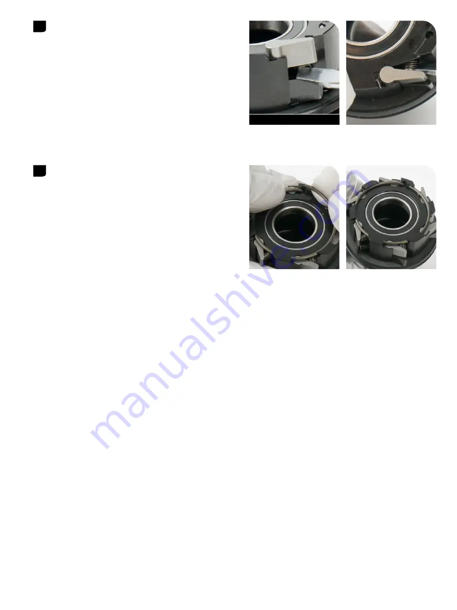
Driver Cleaning (optional) - Coil Spring Driver

Use a small flat blade screwdriver to compress the spring to allow 

the pawl to drop into the slot, then adjust the spring so that it is 

perpendicular to the back of the pawl.
Repeat steps 6-9 to install the other springs and pawls. 

Make sure the black pawls are installed in the lower row of slots.

Orient the end of the snap ring into the hole in the driver and push the 

snap ring onto the channel of the driver until it is fully seated.

Flat blade screwdriver

10 

Summary of Contents for ZM2

Page 1: ...SERVICE MANUAL GEN 0000000006444 Rev C 2022 SRAM LLC ZM2 Hubs ...

Page 2: ...Y NOT APPLY TO YOU LIMITATIONS OF WARRANTY This warranty does not apply to products that have been incorrectly installed adjusted and or maintained according to the respective SRAM user manual The SRAM user manuals can be found online at sram com service This warranty does not apply to damage to the product caused by a crash impact abuse of the product non compliance with manufacturer s specificat...

Page 3: ...VIEW REAR HUB 7 REAR HUB END CAPS 7 REAR HUB BEARING REMOVAL 8 REAR HUB BEARING INSTALLATION 12 DRIVER CLEANING OPTIONAL COIL SPRING DRIVER 16 DRIVER CLEANING OPTIONAL LEAF SPRING DRIVER 19 DRIVER BEARING REPLACEMENT OPTIONAL 21 FRONT HUB SERVICE 23 COMPONENT REMOVAL 23 PARTS TOOLS AND SUPPLIES 23 EXPLODED VIEW FRONT HUB 24 FRONT HUB END CAPS 24 FRONT HUB BEARING REMOVAL 25 FRONT HUB BEARING INSTA...

Page 4: ...SAFETY FIRST We care about YOU Please always wear your safety glasses and protective gloves when servicing SRAM products Protect yourself Wear your safety gear ...

Page 5: ...tures contained in this publication For recycling and environmental compliance information please visit www sram com company environment P a r t P r e p a r a t i o n Remove the component from the bicycle before service Clean the exterior of the product with mild soap and water to avoid contamination of internal sealing part surfaces S e r v i c e P r o c e d u r e s The following procedures shoul...

Page 6: ...es Apron Clean lint free shop towels Nitrile gloves Safety glasses Lubricants and Fluids Isopropyl alcohol Zipp Cognition or Klüber Staburags NBU30 grease SRAM Butter grease Zipp SRAM Tools Zipp 61903 Bearing Press Tool x2 or Zipp 61903 Bearing Press Tool x1 and SRAM 6903 Bearing Press Tool x1 Bicycle Tools Axle and Spindle Vise Inserts Park Tool AV 4 or AV 5 Blind Hole Bearing Puller Set 17 mm sl...

Page 7: ... C a p s DRIVE SIDE NON DRIVE SIDE Hub Variants Current Identification Text On End Cap Previous Identification Text On End Cap Spare Part Kit Number Current Identification Text On End Cap Previous Identification Text On End Cap Spare Part Kit Number ZM2 REAR 12 X 148 6B 10SPD 151 030 12x 142 148 DS XD R 11 2018 064 007 212 000 11 2018 064 007 XD Driver Body SRAM XD Driver Body SRAM 10 11 Speed ...

Page 8: ... the end cap Repeat to remove the other end cap Pull the driver body from the hub by hand Inspect the rubber seal for damage If the seal is damaged replace the driver body Use a plastic mallet to tap the non drive side end of the axle to remove the axle and bearing from the hub Pull the axle and drive side bearing out of the drive side of the hub If the drive side bearing was not removed with the ...

Page 9: ...lat aluminum vise soft jaws drive side down with the bearing resting on top of the soft jaws Make sure the axle bearing step does not contact the soft jaws Use a plastic mallet to gently tap on the top of the non drive end of the axle until it is dislodged from the bearing Discard the bearing NOTICE To avoid damage to the axle do not allow the axle to contact the vise soft jaws If the axle bearing...

Page 10: ...ully pull away from the slotted attachment to remove the bearing from the driver body Insert the 17 mm Bearing Puller slotted attachment through the non drive side bearing Align the slotted attachment with the bottom of the bearing and expand it inside the bearing Do not over tighten the slotted attachment For more detailed assembly and usage see the bearing puller manufacturer s instructions Grip...

Page 11: ...al Clean the bearing bores with isopropyl alcohol and a shop towel Clean the ratchet ring and hub internals with isopropyl alcohol a shop towel and cotton swabs Do not remove the ratchet ring 10 Isopropyl Alcohol Shop Towel 11 ...

Page 12: ... 30x17 tool onto the threaded rod Thread the Press Tool handle onto the threaded rod Turn the handle clockwise to press the bearing into the hub until it is hand tight Do not overtighten the bearing Remove the tools NOTICE To prevent damage when pressing the bearing into the hub make sure that the bearing press tools contact both the inner and outer bearing races or bearing bores and not the hub s...

Page 13: ...on stepped end of the tool against the bearing Install the non drive side end of the axle through the hub and into the SRAM 6903 tool Install a Zipp 61903 tool onto the drive side end of the axle with the stepped end of the tool contacting the bearing Use a rubber mallet to tap the drive side of the axle until the raised step on the axle contacts the bearing Remove the tool from the axle 4 Plastic...

Page 14: ...rease or on the part Install the driver body onto the axle and twist it counter clockwise to seat the driver body and driver body seal Make sure the driver body seal is fully seated into the seal groove The installation process is the same for 10 speed and XD driver bodies Install the wave spring onto the non drive side of the axle You may need a tool to press the wave spring against the bearing f...

Page 15: ...urface b Bearing front face across bearing seal inner and outer ring c NOTICE If a brush is used to apply grease confirm there are no loose bristles in the grease or on the part Press the end caps onto the axle Clean the hub with isopropyl alcohol and a shop towel Cognition Klüber Staburags NBU30 grease a c b 12 a c b 13 14 Shop towel Isopropyl alcohol ...

Page 16: ... XDR Freilaufs Prüfen Sie die Gummidichtung auf Beschädigungen Wenn die Dichtung beschädigt ist tauschen Sie den Freilauf aus Heben Sie mit den Fingern oder einem kleinen Schlitzschraubendreher den Sprengring aus dem Freilauf Entfernen Sie mit den Fingern einem Dorn oder einer Spitzzange die Sperrklinken und Schraubenfedern aus dem Freilauf Säubern Sie die Sperrklinken Nuten mit einem Wattestäbche...

Page 17: ...gen Ausrichtung montiert werden Drücken Sie die Feder mit einem kleinen Schlitzschraubendreher zusammen damit die Sperrklinke in die Nut fallen kann und justieren Sie dann die Feder so dass sie senkrecht zur Rückseite der Sperrklinke steht Setzen Sie eine Schraubenfeder in die obere Federnut über der zuvor installierten Sperrklinke Feder ein und montieren Sie dann eine silberne Sperrklinke in der ...

Page 18: ...dass sie senkrecht zur Rückseite der Sperrklinke steht Wiederholen Sie die Schritte 6 bis 9 um die anderen Federn und Sperrklinken einzubauen Stellen Sie sicher dass die schwarzen Sperrklinken in der unteren Nutenreihe installiert werden Richten Sie das Ende des Sprengrings auf die Bohrung im Freilauf aus und drücken Sie den Sprengring in den Kanal des Freilaufs bis er ordnungsgemäß sitzt 9 Schlit...

Page 19: ... XDR Freilaufs Prüfen Sie die Gummidichtung auf Beschädigungen Wenn die Dichtung beschädigt ist tauschen Sie den Freilauf aus Heben Sie mit den Fingern oder einem kleinen Schlitzschraubendreher den Sprengring aus dem Freilauf Entfernen Sie mit den Fingern einem Dorn oder einer Spitzzange die Sperrklinken und Schraubenfedern aus dem Freilauf Säubern Sie die Sperrklinken Nuten mit einem Wattestäbche...

Page 20: ...gen Ausrichtung montiert werden Drücken Sie die Feder mit einem kleinen Schlitzschraubendreher zusammen damit die Sperrklinke in die Nut fallen kann und justieren Sie dann die Feder so dass sie senkrecht zur Rückseite der Sperrklinke steht Setzen Sie eine Schraubenfeder in die obere Federnut über der zuvor installierten Sperrklinke Feder ein und montieren Sie dann eine silberne Sperrklinke in der ...

Page 21: ...dass sie senkrecht zur Rückseite der Sperrklinke steht Wiederholen Sie die Schritte 6 bis 9 um die anderen Federn und Sperrklinken einzubauen Stellen Sie sicher dass die schwarzen Sperrklinken in der unteren Nutenreihe installiert werden Richten Sie das Ende des Sprengrings auf die Bohrung im Freilauf aus und drücken Sie den Sprengring in den Kanal des Freilaufs bis er ordnungsgemäß sitzt 9 Schlit...

Page 22: ... XDR Freilaufs Prüfen Sie die Gummidichtung auf Beschädigungen Wenn die Dichtung beschädigt ist tauschen Sie den Freilauf aus Heben Sie mit den Fingern oder einem kleinen Schlitzschraubendreher den Sprengring aus dem Freilauf Entfernen Sie mit den Fingern einem Dorn oder einer Spitzzange die Sperrklinken und Schraubenfedern aus dem Freilauf Säubern Sie die Sperrklinken Nuten mit einem Wattestäbche...

Page 23: ...gen Ausrichtung montiert werden Drücken Sie die Feder mit einem kleinen Schlitzschraubendreher zusammen damit die Sperrklinke in die Nut fallen kann und justieren Sie dann die Feder so dass sie senkrecht zur Rückseite der Sperrklinke steht Setzen Sie eine Schraubenfeder in die obere Federnut über der zuvor installierten Sperrklinke Feder ein und montieren Sie dann eine silberne Sperrklinke in der ...

Page 24: ...dass sie senkrecht zur Rückseite der Sperrklinke steht Wiederholen Sie die Schritte 6 bis 9 um die anderen Federn und Sperrklinken einzubauen Stellen Sie sicher dass die schwarzen Sperrklinken in der unteren Nutenreihe installiert werden Richten Sie das Ende des Sprengrings auf die Bohrung im Freilauf aus und drücken Sie den Sprengring in den Kanal des Freilaufs bis er ordnungsgemäß sitzt 9 Schlit...

Page 25: ...service shown below Inspect the rubber seal for damage If the seal is damaged replace the driver Use your fingers or a small flat blade screwdriver to lift the snap ring from the driver Use your fingers a pick or needle nose pliers to remove the pawls and coil springs from the driver Clean the pawl slots with a cotton swab and the driver body with isopropyl alcohol and a shop towel 1 2 3 4 ...

Page 26: ... can be installed in any orientation Use a small flat blade screwdriver to compress the spring to allow the pawl to drop into the slot then adjust the spring so that it is perpendicular to the back of the pawl Insert a coil spring into the upper spring slot above the previously installed pawl spring then install a silver pawl into the pawl slot Note The springs and pawls are symmetrical and can be...

Page 27: ...ust the spring so that it is perpendicular to the back of the pawl Repeat steps 6 9 to install the other springs and pawls Make sure the black pawls are installed in the lower row of slots Orient the end of the snap ring into the hole in the driver and push the snap ring onto the channel of the driver until it is fully seated 9 Flat blade screwdriver 10 ...

Page 28: ...own below Inspect the rubber seal for damage If the seal is damaged replace the driver Use a small flat blade screwdriver to lift the snap ring from the driver Use a pick or needle nose pliers to remove the pawls and leaf springs from the driver Using a grease syringe apply a small amount of SRAM Butter grease to the pawl slots 1 2 Flat Head Screwdriver 3 Needle nose Pliers Pick 4 SRAM Butter Grea...

Page 29: ...uld slide in easily Forcing the spring into the slot can bend or damage the spring requiring replacement of the driver Insert the black pawls into the pawl slots followed by the silver pawls Use a pick or flat blade screwdriver to compress each leaf spring to assist with inserting the pawls Orient the end of the snap ring into the hole in the driver and push the snap ring onto the channel of the d...

Page 30: ...hment through the inboard bearing Align the slotted attachment with the bottom of the bearing and expand it inside the bearing Do not over tighten the slotted attachment For more detailed assembly and usage see the bearing puller manufacturer s instructions Thread the rod of the bearing puller into the attachment Grip the slide hammer and forcefully pull away from the slotted attachment to remove ...

Page 31: ...3 61803 driver bearing into the inboard side of the driver body with the black seal facing outward Note Ceramic bearings have blue seals on both sides of the bearing installation orientation is not important Insert a 6803 26x17 tool onto the bearing Insert the threaded rod through the bearing on the inboard side of the driver Slide a second 6803 26x17 tool onto the threaded rod Thread the Press To...

Page 32: ...BEARING KIT FRONT REAR FOR ZIPP ZR1 ZM2 HUBS 61903 WHEEL AXLE END CAP SET FRONT 15X110 BOOST ZM2 HUBS WHEEL AXLE END CAP SET FRONT 15X110 BOOST TORQUE CAP ROCKSHOX FORKS ZM2 HUBS Safety and Protection Supplies Apron Clean lint free shop towels Nitrile gloves Safety glasses Lubricants and Fluids Isopropyl alcohol Cognition Klüber Staburags NBU30 grease SRAM Butter grease Bicycle Tools Axle and Spin...

Page 33: ...ub Variants Current Identification Text On End Cap Previous Identification Text On End Cap Spare Part Kit Number Current Identification Text On End Cap Previous Identification Text On End Cap Spare Part Kit Number ZM2 FRONT 15 x 110 6B 165 010 15x 100 110 DS DISC 11 2018 064 001 165 010 15x 100 110 DS DISC 11 2018 064 001 15 x 110RS 189 000 15x 100 110 RS DS 6B 11 2018 064 002 189 000 15x 100 110 ...

Page 34: ...le end with a plastic mallet to dislodge the axle from the hub bearings Use your thumb to push the axle through the hub shell and remove the wave spring from the non drive side hub shell NOTICE Do not discard or misplace the wave spring It is crucial to hub performance and the hub will not fuction properly without the spring Remove the front axle from the drive side of the hub Use your fingers to ...

Page 35: ...e bearing puller manufacturer s instructions Grip the slide hammer and forcefully pull away from the slotted attachment to remove the bearing from the hub shell Insert the 17 mm Bearing Puller slotted attachment through the non drive side bearing Align the slotted attachment with the bottom of the bearing and expand it inside the bearing Do not over tighten the slotted attachment For more detailed...

Page 36: ...36 Front Hub Bearing Removal Clean the hub shell with isopropyl alcohol and a shop towel 7 Isopropyl Alcohol Shop Towel ...

Page 37: ...6903 30x17 tool onto the threaded rod Thread the Press Tool handle onto the threaded rod Turn the handle clockwise to press the bearing into the hub until it is hand tight Do not overtighten the bearing Remove the tools NOTICE To prevent damage when pressing the bearing into the hub make sure that the bearing press tools contact both the inner and outer bearing races or bearing bores and not the h...

Page 38: ...e clockwise to press the bearing into the hub until it is hand tight Do not overtighten the bearing Remove the tools Apply grease to the non drive side axle bearing race Insert the non drive side end of the axle into the drive side of the hub through the drive side bearing through the hub and through the non drive side bearing Press the axle into the hub bearing with your thumb until the axle bear...

Page 39: ...ing The wave spring is crucial to hub performance and must be installed onto the axle Apply grease to the following locations on the drive side and non drive side axle end Axle front surface a Axle radial surface b Bearing front face across bearing seal inner and outer ring c Press the end caps onto the axle Clean the hub with isopropyl alcohol and a shop towel 7 8 Klüber Staburags NBU30 grease a ...

Page 40: ... Hexfin HollowPin Howitzer HRD Hybrid Drive Hyperfoil i 3 Impress Jaws Jet Kage Komfy LINK Lyrik MatchMaker Maxle Maxle 360 Maxle DH Maxle Lite Maxle Lite DH Maxle Stealth Maxle Ultimate Micro Gear System Mini Block Mini Cluster Monarch Monarch Plus Motion Control Motion Control DNA MRX MX Noir NX OCT OmniCal OneLoc Paceline Paragon PC 1031 PC 1110 PC 1170 PG 1130 PG 1050 PG 1170 Piggyback Poploc ...

Page 41: ...1598 8 Chung Shan Road Shen Kang Hsiang Taichung City Taiwan R O C WORLD HEADQUARTERS SRAM LLC 1000 W Fulton Market 4th Floor Chicago Illinois 60607 U S A EUROPEAN HEADQUARTERS SRAM Europe Paasbosweg 14 16 3862ZS Nijkerk The Netherlands ...

Reviews: