background image

16  |  Installation Instructions

6.  Connect Ethernet cable to back of the unit if any remote monitoring of the Battery Cabinet is desired.

a.  Configuration details are provided in the Operations Manual.

7.  Apply AC Power to the system

a.  It will take approximate 1-3 minutes for the BMS/R3000 to initialize and communicate with the server.

• 

The network requirements needed for the R3000 to communicate with the Cloud or Local server:

1. 

Local DHCP assigned IPv4 address 


Inbound and Outbound permit TCP/443 and TCP/9101 to:

  139.177.197.251

  173.255.231.159

  172.105.103.167

  45.33.95.14

2. 

Outbound permit tcp/3030, tcp/9101 to 172.105.23.38

b.  If using the Cloud server, go to website to verify system is online: https://manage.anzenbms.com/

c.  The system will begin in “Pre-standby state” until DC Power is applied

d.  Confirm all batteries are /-0.3V of one another. Since all batteries ship between 50% State of Charge it  


is likely the batteries will be around 14.0 +/- 0.3V.

8.    Enable the DC Power (UPS/Charger)

a.  Ensure UPS or battery charger is set properly to manufacturers recommended settings for operation with

the battery system.

b.  Close the Breaker with the system in the “Pre-standby State.”The system will immediately go into “Standby 


state” which means it is ready to function.

c.  The system will transition immediately into a “Charge State” if the SOC is below 90% and battery 


temperatures are all 15C to 40C.

9.    Perform a full or partial discharge (if possible) to confirm the system is working properly.

a.  Confirm system shuts down properly with no system errors.

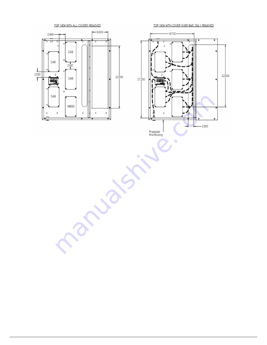
Figure 10. BMS Wiring

Summary of Contents for BC Series

Page 1: ...Installation Instructions ZincFive BC Series UPS Battery Cabinets Copyright 2022 ZincFive Inc All rights reserved ZincFive BC Series UPS Battery Cabinet...

Page 2: ...Copyright 2022 ZincFive Inc All rights reserved...

Page 3: ...Manual 5 Save this Manual 5 Disclaimer Safety 6 Safety Symbols 7 Battery Safety 8 Battery Warnings and Cautions Specifications Safety Precautions Tools Pr cautions de s curit Outils Shipping and Unpac...

Page 4: ...product returns please contact a ZincFive support representative to obtain a return material authorization RMA ZincFive Inc 20170 SW 112th Ave Tualatin Oregon 97062 Customer is responsible to properly...

Page 5: ...ort representative visit zincfive com support or call 888 517 7776 Disclaimer While efforts have been made to ensure the accuracy and validity of information contained in the document ZincFive assumes...

Page 6: ...AND BATTERIES FAILURE TO HEED THESE INSTRUCTIONS AND WARNINGS WILL VOID YOUR WARRANTY CAUTION Important information or operating instructions Follow them exactly Protective Earth Ground Symbol Used t...

Page 7: ...sulated handles c Wear rubber gloves and boots d Do not lay tools or metal parts on top of batteries e Disconnect charging source and load prior to installing or maintaining the battery f Remove batte...

Page 8: ...75 C OR INCINERATE French PROT GER LES YEUX EN TOUT TEMPS AVEC UN QUIPEMENT DE PROTECTION PAS D TINCELLES OU DE FLAMMES INTERDICTION DE FUMER LECTROLYTES ALCALINS RINCER LES YEUX IMM DIATEMENT AVEC DE...

Page 9: ...n SOC with extended storage the batteries must not be stored more than six months without recharging If attached to a UPS that remains de energized for a long period ZincFive recommends you energize t...

Page 10: ...sage de longue dur e il ne faut pas entreposer les batteries plus de six mois sans les recharger Si reli une ASI qui reste inerte pendant une p riode prolong e ZincFive vous recommande d alimenter l A...

Page 11: ...place 4 Perform a visual inspection of the cabinet a Open the door and examine all the batteries drawers to make sure everything is still secure and attached Note Drawers are locked in place with two...

Page 12: ...cluding eye protection The cabinet voltage will exceed 500V between some of the batteries components 1 Inspection of the Batteries installed a Visual inspection of battery strings cables Confirm nothi...

Page 13: ...nductors to the circuit breaker a Make sure all power is off before making connection b Positive conductor s will be attached to Terminal 4 Bottom of circuit breaker c Negative conductor s will be att...

Page 14: ...orque screws to 0 6 0 8Nm 5 31 7 08 in lb c Note The AC power MUST be supplied by a 100Watt UPS backed circuit This powers the BMS and must remain powered when in backup during a power outage for the...

Page 15: ...nfigured with an UVR access the circuit breaker cannot be turned on until UPS outputs its rated UVR voltage When the battery cabinet is configured with a shunt access the circuit breaker will trip whe...

Page 16: ...stem is online https manage anzenbms com c The system will begin in Pre standby state until DC Power is applied d Confirm all batteries are within 0 3V of one another Since all batteries ship between...

Page 17: ...Installation Instructions 17 Appendix A...

Page 18: ...18 Installation Instructions Appendix B...

Page 19: ...Installation Instructions 19 Appendix C...

Page 20: ...20 Installation Instructions Notes...

Page 21: ...Copyright 2022 ZincFive Inc All rights reserved...

Page 22: ...ZincFive Inc 20170 SW 112th Ave Tualatin Oregon 97062 zincfive com support 01100 00400 00100 rev H00 Copyright 2022 ZincFive Inc All rights reserved...

Reviews: