background image

Zimmer GmbH 

 Im Salmenkopf 5 

 77866 Rheinau, Germany 

 Phone: +49 7844 9138-0 

●  

Fax: +49 7844 9138-80 

 www.zimmer-group.de

DDOC00198/t

EN/2015-10-07

7

INSTALLATION AND OPERATING INSTRUCTIONS: 

ELECTRIC GRIPPER GEP/GED5000 SERIES

7.4 

End positions


INFORMATION:


Important for handling the product.


The setting of the intermediate position (Section 6.3) is lost when teaching-in the end positions!


After teaching-in the end positions, the intermediate position must be taught-in once again!

End position confirmation occurs via pin 2 (work position)* and pin 5 (base position)*.

The statuses are visualized on the gripper via the LED display.

The gripper's end position sensing is preset by the plant. 

If necessary, end positions can be re-set via an automatic traversing routine*.

► To do so, a signal (+24 V DC) must be applied to the pin 7 output (teach/adjust)* for at least 15 seconds.


 A requirement is that the DIR signal is simultaneously set to "0".

► After approximately 3 seconds, the traversing routine* begins and is completed after 5 gripping cycles.

*) See "Glossary" section for definitions


NOTE:


Non-compliance may result in damage to the system


If the signal (+24 V DC) is interrupted before the end of the traversing routine, the procedure must be repeated 

because the end positions are not correctly determined.

7.5 

Minimum travel path

The gripper requires a minimum travel path of 

> 1,25 mm

 per jaw before it is permitted to reach a workpiece.


 Failure to do so means the gripper cannot establish the desired gripping force and displays an error.

The minimum travel path applies to both movement directions and is independent of the gripper's starting position.

8. Operation

8.1 

Control panel

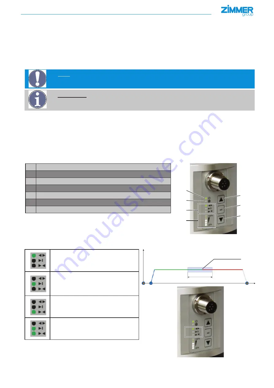
The control panel of the gripper continuously displays the current status of the device and provides the option to modify various set

-

tings of the gripper using multiple menus

1

2

3

4

5

6

7

1

Power LED, power supply

2

Error LED, error display

3

Position display, menu display

4

Parameter display, binary error code display

5

Plus key, increase parameter value

6

Set button

7

Minus key, decrease parameter value

8.2 

Position display

The positions of the gripper are displayed on the operator panel via three LEDs.

Gripper in base position

NC = gripper jaws open

NO = gripper jaws closed

Gripper is on a teached-in workpiece item 

(teach-in position/teach position)

Gripper is at the work position

(working position)

If the gripper has been taught-in at an end posi-

tion, two LEDs are switched on simultaneously.

(Ex.: End position, work position and teach 

position

Base position

Work position

Teach position

Summary of Contents for GEP5000 Series

Page 1: ...INSTALLATION AND OPERATING INSTRUCTIONS Handling Technology GEP GED5000 series Electric gripper THE KNOW HOW FACTORY...

Page 2: ...aused by improper use 2 Proper use The gripper is designed exclusively for electric operation using a supply voltage of 24 V DC The gripper is used as defined under Proper use in enclosed rooms to tem...

Page 3: ...ves at high speed back into the starting position The gripper is suitable for inward gripping NC normaly closed This means the gripper moves at high speed back into the starting position NC NO 4 1 GEP...

Page 4: ...e carried out to install the gripper Insert centering sleeves into the provided matching parts on the gripper Position the gripper on the designated mounting surface using the centering sleeves Secure...

Page 5: ...on the energy consumption of the gripper is 150 mA The parameters can be set using the arrow keys on the membrane keyboard see section 7 3 Pin Color Function Explanation 1 White DIR INPUT open close g...

Page 6: ...wn on the gripper via the LED display See Glossary section for definitions Course of action for teaching the gripper with workpiece Put the gripper jaws into the desired position for instance by inser...

Page 7: ...aversing routine the procedure must be repeated because the end positions are not correctly determined 7 5 Minimum travel path The gripper requires a minimum travel path of 1 25 mm per jaw before it i...

Page 8: ...e Changing the value Changing the value Changing the value Call up the main menu by pressing SET 3 seconds The menu display LEDs will flash You can access the edit mode of a value by pressing SET once...

Page 9: ...ycle time 3 NO operation outward gripping with the desired force mode quick inward movement for reducing the cycle time Default value 1 If the gripping direction is defined the corresponding gripper m...

Page 10: ...ase contact ZIMMER GmbH Customer Service For this purpose please call our technology hotline at 49 7844 9138 0 8 6 2 Menu 2 Width teach area GEP5006 GED5006 Teach area Width mm Teach area width 1 0 2...

Page 11: ...ng mode GEP5006 GED5006 Force setting Value 1 Value 2 Value 3 Value 4 Value 5 Gripping force during closing N 540 620 710 860 960 Gripping force during opening N Travel time during closing s 0 22 0 2...

Page 12: ...8 GED5008 Force setting Value 1 Value 2 Value 3 Value 4 Value 5 Gripping force during closing N 650 790 920 1090 1150 Gripping force during opening N Travel time during closing s 0 29 0 27 0 25 0 22 0...

Page 13: ...ode GEP5010 GED5010 Force setting Value 1 Value 2 Value 3 Value 4 Value 5 Gripping force during closing N 980 1080 1200 1400 1520 Gripping force during opening N Travel time during closing s 0 32 0 29...

Page 14: ...m Teach area offset 1 0 8 mm Teach area offset 2 0 4 mm Teach area offset 3 0 mm Teach area offset 4 0 4 mm Teach area offset 5 0 8 mm GEP5010 GED5010 Position teach area Offset mm Teach area offset 1...

Page 15: ...in menu must be selected to see the error code The five lower LEDs represent the current error code in binary form In the following example error code 7 is active The error is acknowledged via a new D...

Page 16: ...s work base or teach in position Check the object being gripped or the gripper jaws 9 Gripper does not reach the target speed Difficulty moving the guide Zimmer Group Service 10 The jaw position senso...

Page 17: ...the target speed when approaching Difficulty moving the guide Zimmer Group Service 18 Gripper is in NC or NO mode and is blocked from free run see Section 7 5 menu 3 menu function Gripper is difficult...

Page 18: ...ding signature Managing Partner 11 Declaration of Incorporation in the context of EU Machinery Directive 2006 42 EC Annex II 1 B Name and address of the manufacturer ZIMMER GmbH Im Salmenkopf 5 D 7786...

Page 19: ...n Base position of the gripper DC motor Motor run on DC power DIR Direction 24 V supply line Error Fault error message ESD Electrostatic discharge electrostatic sensitivity GED Gripper electrically po...

Reviews: