

MS220K and MSR220K
10750-0702-00
Page
7 / 8
www.ziehl.de
10
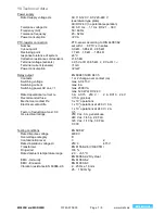
Technical data
Power supply
Rated supply voltage Us
AC 110-120 V, AC 220-240 V
(see lateral type plate)
AC/DC 24 V (no potential separation)
Tolerance voltage Us
AC 0,9 Us … 1,1 Us DC 21 ... 30 V
Frequency (AC)
50 / 60 Hz
Tolerance frequency
45 - 62 Hz
Power consumption
<2 VA
PTC-resistor connection
PTC-sensor according to DIN 44081/82
Number
set with 1 ... 6 PTC´s in series
Cut-out-point
3,3 kΩ…3,65 kΩ…3,85 kΩ
Reclosing point
1,7 kΩ…1,8 kΩ …1,95 kΩ
response tolerance of system
±6 °C
Collective resistance cold sensors
≤1,65 kΩ
Terminal voltage (sensors)
≤ 2,5 V at R ≤3,65 kΩ, ≤ 9 V at R =
Terminal current (sensors)
<1 mA
Power consumption
<2 mW
Relay output
EN 60947-5/IEC 947-5
Contacts
1 or 2 change-over contact (co)
Switching voltage
max. AC 415 V
Switching current
max. 6 A
Switching power AC cos = 1
max. 2000 VA
max. 120 W at DC 24 V
Rated operational current Ie
3 A AC15 250 V ;
2 A DC13 24 V
Recommended fuse
3,15 A gl (slow)
Mechanical contact life
3 x 10
7
operations
Electrical contact life
1 x 10
5
operations at 240 V / 6 A
1 x 10
6
operations at 240 V / 2 A
Factor of reduction at cos=0,3
0,5
UL electrical ratings
250 V ac, 3 A, general use
240 V ac, 1/4 hp, 2.9 FLA
120 V ac, 1/10 hp, 3.0 FLA
C 300
Testing conditions
EN 60 947
Rated impulse voltage
4000 V
Overvoltage category
III
Contamination level
3
2
Rated insulation voltage Ui
250 V
415 V
Transformer
EN 61558-2-6 (VDE 0551)
On-period
100 %
Rated ambient temperature range
-20 ... +55 °C
EN 60068-2-2 Dry Heat
EMC - Immunity
EN 61000-6-2
EMC - Emission
EN 61000-6-3
Vibration resistance EN 60068-2-6
2…25 Hz ±1,6 mm
25 ... 150 Hz 5g