


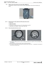

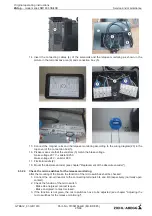


8.3.2.5Adjusting the micro switches for the release monitoring
Required tool for adjusting the micro switches:
•
Circuit inductor
•
screw wrench SW 7
•
screw wrench SW16
•
Feeler gauge 0,12 mm
•
Feeler gauge 0,16 mm
•
Feeler gauge 0,2 mm
The adjusting is only necessary if the micro switches are not working correctly.
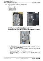
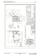
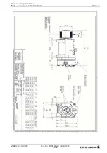
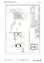
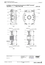
The micro switches are on the side of the brake body (see arrows).
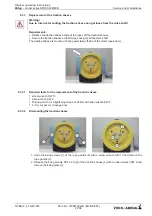
WARNING! Ensure that you select the appropriate micro switch for the magnet to be adjusted.
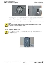
1. De-energize the brake.
2. Loosen the hexagon head screw (15) with screw wrench SW 16 and remove the cover plate (16)
of the micro switch. The parts are reused.
3. Connect the circuit inductor to the connecting terminals 3/4 and 8/9 respectively (normally open
contact).
4. Please see the chapter "Enclosure - Brake operation instructions" for the further procedure for
setting the micro switches for the release monitor.
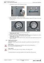
5. After making the correct setting, apply locking varnish to adjusting screw.
6. Fasten the cover plate (16) of the micro switch with the hexagon head screw (15) and a screw
wrench SW 16
Service and maintenance
$7%$B*%
Part.-No. 01008166-GB (
EU-BD 845
)
26/68
2ULJLQDORSHUDWLQJLQVWUXFWLRQV
ZAtop
–
model series SM160.30B/40B


