


•
Metal screwed-connections are not permitted in plastic housing parts because there is no potential
equalization.
•
Care must be taken to avoid direct radiation from the sun!
•
The device is designed for vertical installation (bottom cable inlet). A horizontal or reclined installa-
tion is only permissible after technical release of the manufacturer!
•
Be sure to observe proper heat dissipation (see Technical data, heat dissipation).
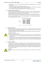
4.2
Minimum space requirement
In order to ensure suf
fi
cient ventilation of the device, clearance on all sides of at least 50 mm has to
be maintained to the housing walls, switch cabinet doors, wiring ducts, etc. The same clearance
applies to the installation of several devices next to each other.
When installing several devices on top of each other, the danger of reciprocal heating exists. This
layout is only then permissible when the air suctioned from the upper unit does not become warmer
than the permissible ambient temperature (see Technical data). I.e., a correspondingly larger clear-
ance or thermal shielding is required.
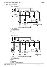
4.3
Mains connection
Power from the mains is connected to terminals: PE, L1, L2, L3 and N (only for 400 V version). Here, it
must be strictly observed that the mains voltage lies within the allowable tolerance speci
fi
cations (see
Technical data and nameplate af
fi
xed to the side).
The mains voltage must comply with the EN 50160 quality characteristics and the de
fi
ned standard
voltages in IEC 60038!
Danger due to electric current
•
The internal transformer is not short-circuit-proof, note: maximum size of line fuse detailed in the
operating instructions. When using automatic circuit breakers, you must use a 3-poled type with
“
C
”
characteristics.
•
To prevent transformer overloading, exclude two-phased conductance by taking measures at the
customer location. Alternative to phase monitoring, a motor overload protector with phase-failure
sensitivity can be used as the backup fuse. Set it to the rated current of the transformer-induced
control device.
4.4
Motor connection
The motor leads are connected to the terminals: PE, U, V, W. Several fans can be connected to the
controller-the maximum total current of all motors must not exceed the current rating for the controller.
Motor protection via connection of TB thermostatic switches (not suitable for PTC thermistors). When
the thermostatic switches are triggered (motor fault), the device switches off. Restart is performed
once the drive has cooled down either by switching the mains voltage off and on again (after approx. 2
minutes) or via the switch.
Attention!
If multiple motors are connected, connect thermostatic switches to the TB-TB (TK-TK) terminals in
series.
Operating Instructions
R-DT-.., RTRD.., RUDT..
Installation
L-BAL-E285-GB 1907 Index 002
Part.-No.
6/12


