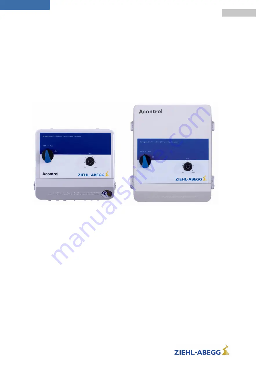
Acontrol
PXET6Q / PXET10Q
Multipurpose controller for variable voltage 1 ~ fans
Operating Instructions
Keep for reference!
Software version: B1061AA from version 1.01
L-BAL-E016-GB 1925 Index 007
Part.-No.
english
Библиотека СОК
Page 1: ...ntrol PXET6Q PXET10Q Multipurpose controller for variable voltage 1 fans Operating Instructions Keep for reference Software version B1061AA from version 1 01 L BAL E016 GB 1925 Index 007 Part No engli...
Page 2: ...ulture 8 4 5 Temperature in uences during commissioning 8 5 Electrical installation 8 5 1 Safety precautions 8 5 2 EMC compatible installation 9 5 2 1 Motor cable 9 5 2 2 Control cables 9 5 2 3 Harmon...
Page 3: ...r operation as Temperature controller 20 9 2 2 Example Temperature control Cooling function factory setting 21 9 2 3 Example Temperature control Heating function 21 9 3 Pressure control condensers P C...
Page 4: ...software in the device has been examined It is still possible that non compliances exist no guarantee is assumed for complete conformity To allow for future developments construction methods and techn...
Page 5: ...instructions of AEL DLG VdS 2 4 Requirements placed on the personnel due diligence Persons entrusted with the planning installation commissioning and maintenance and servicing in connection with the...
Page 6: ...use 2 8 Operator s obligation of diligence The contractor or owner must also ensure that the electric systems and equipment are operated and maintained in accordance with electro technical regulations...
Page 7: ...amage Start up is not allowed in the case of transport damage At a weight greater than 25 kg for men 10 kg for women the device should be lifted out by two persons according to REFA The values may dif...
Page 8: ...ions Danger due to electric current Work on electric components may only be carried out by trained electricians or by persons instructed in electricity under the supervision of an electrician in accor...
Page 9: ...ered to with no restrictions Exception for Germany An energy provider follows the technical connection conditions of the TAB2007 in which case the use of phase angle controlled devices up to a rating...
Page 10: ...or remote control ON OFF enable Attention An outside voltage may never be connected to the terminals TB If a bypass circuit is installed or in the 100 position on devices with a main switch the motor...
Page 11: ...Controller or PI Controller function for D1 can be selected with DIP 8 5 8 Voltage supply for external devices 24V GND A voltage supply is integrated for external devices e g a sensor max current loa...
Page 12: ...indicated for line fault blown internal semiconductor fuse broken controller internal voltage supply overheating by the motor thermostats TB connected By sensor failure only in P Control or PI Contro...
Page 13: ...2 and selected mode For Speed controller 1 01 always without function For the P controller 2 01 3 01 and PI controller 4 01 the DIP 2 switch can be used to select whether the set value setting can be...
Page 14: ...active at the factory DIP 2 OFF For temperature control 2 01 with passive sensors TF KTY setting range 0 100 26 76 C measuring range of controller For control with active sensors 3 01 4 01 0 10 V 4 2...
Page 15: ...ns become active partly only after renewed switching on the mains voltage E1 Analog In factory setting 0 10 V 13 03 2012 v_jumper_e1_dip_s1_mode vsd A E1 GND 0 10 V 10 k E1 GND TF TF KTY 3 1 BN GN 24V...
Page 16: ...the sensor is compared with the nominal value that has been set The output voltage and hence the rotational speed of the connected motor automatically change as a function of the parameter settings T...
Page 17: ...ith minimum speed cut off DIP 5 ON When the setpoint is reached the modulation is reduced to 0 or to the set value if n min is speci ed For actual value setpoint disconnection takes place from n min t...
Page 18: ...or external potentiometer DIP 2 OFF factory setting Setting range Output voltage from approx 0 100 of connected line voltage or in range of settings n min up to n max Potentiometer set without functi...
Page 19: ...two steps DIP2 OFF for setting via external signall Switchover between two steps via external potential free contact possible Step 1 low speed When there is no input signal connected to the input term...
Page 20: ...5 8 76 0 Scale 0 100 26 76 C for Temperature control with passive sensors TF KTY set 0 5 10 15 20 25 30 35 40 45 50 55 60 65 70 75 80 85 90 95 100 C 26 0 20 9 15 8 10 7 5 6 0 5 4 6 9 7 14 8 19 9 25 0...
Page 21: ...n min 35 n max 85 Idealized principle diagram 9 2 3 Example Temperature control Heating function Val Set n DIP4 ON Temperature sensor type TF Measuring range controller 26 76 C Settings set 50 25 C 10...
Page 22: ...08 v_pxet_q_skala_mbg30 VSD set 0 10 20 30 40 50 60 70 80 90 100 bar 0 0 3 0 6 0 9 0 12 0 15 0 18 0 21 0 24 0 27 0 30 0 19 07 2011 v_pband_pxet VSD Pband 5 30 Pband Pband Narrow control range Short co...
Page 23: ...of refrigerant medium table for R507 Pband 10 3 0 bar U Motor 50 100 bar C 50 15 bar 34 28 C 507 Set Pband 10 12 03 2008 v_diagramm_bar_c vsd 18 bar 41 53 C 507 n min 0 n max 100 n min 35 n max 85 Ide...
Page 24: ...7 54 25 58 41 62 30 65 96 69 41 72 70 75 82 78 81 81 68 84 44 87 09 89 66 R401A C 29 21 6 93 6 40 16 33 24 39 31 26 37 28 42 68 47 59 52 10 56 29 60 22 63 91 67 40 70 72 73 88 76 91 79 81 82 60 85 29...
Page 25: ...ala_mal1 VSD set 0 10 20 30 40 50 60 70 80 90 100 m s 0 0 0 1 0 2 0 3 0 4 0 5 0 6 0 7 0 8 0 9 1 0 19 07 2011 v_pband_pxet VSD Pband 5 30 Pband Pband Narrow control range Short control times Wide contr...
Page 26: ...Motor fault Tripping of connected thermostat or break between terminals TB The unit cuts out and does not switch on again Check motor and connection then reset Motor protection 3 energized Terminals 1...
Page 27: ...230 V 15 10 50 60 Hz 230 V Input resistance for sensor or signal set for the rotational speed for 0 10 V input Ri 100 k for 4 20 mA input Ri 100 Output voltage approx 0 100 of applied mains voltage M...
Page 28: ...e the rated temperature see following table The average value measured during a 24 h period must be 5 K under the max ambient temperature For installation in a switch cabinet the device s dissipation...
Page 29: ...usgang Output 0 10 V Imax 10 mA 3 Eingang Input 0 10 V 0 20 mA 4 20 mA TF KTY 4 1 2 5 E1 V mA C 1 Line 1 230 V 50 60 Hz 2 1 Motor with internal thermostats 3 Output 0 10 V Imax 10 mA 4 Input 0 10 V 0...
Page 30: ...11 3 Dimensions mm PXET6Q PXET10Q Operating Instructions Acontrol model series PXET6Q PXET10Q Enclosure L BAL E016 GB 1925 Index 007 Part No 30 32...
Page 31: ...5 M mains connection 9 mains voltage 9 maximum control current 9 MBG 30I 21 Minimum space requirement 7 Minimum speed cut off 16 Mode 14 motor feed cable 9 motor noise 9 motor protection unit 9 O Outd...
Page 32: ...o ziehl abegg de http www ziehl abegg de 11 6 Service information If you have any technical questions while commissioning or regarding malfunctions please contact our technical support for control sys...