-4-
A. Preparation for Mounting (continued)
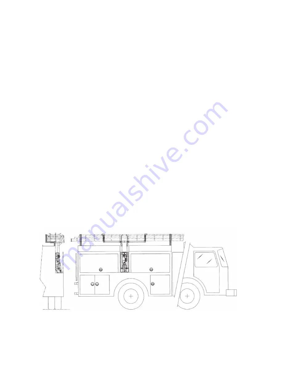
Plan and lay out the entire installation before making any cuts or drilling holes in the body of the
fire apparatus. This will keep "out of service" time to a minimum and also help to minimize mistakes.
Position the unit on the shelf of the apparatus and clamp it in place so that you can determine where
the holes will be required for the mounting bolts. Also check to be sure there is an integral component of
the body structure to attach the mounting bolts through. If there is no main frame member, you may have to
add a 1/2" thick aluminum mounting plate and attach it to a main frame member. Place the ladders on top
of the ladder rack.
When the ladder is raised and lowered in this position, it should clear protruding objects on the
apparatus, such as emergency light, hand rails, etc. Make sure that when the ladders are in the up position
they do not obstruct cross lays on hose reels.
In the event that the booms come into contact with the stiffening rib at the top of the vertical hose bed
wall, you may have to notch out the stiffening rib to recess the HLAS System. If the stiffening rib must be
notched, the exposed metal surfaces should be painted and covered with an edge guard material. In
addition, if the stiffening rib is notched, you may wish to add a backing plate on the inside surface of the
hose bed wall. The plate will reinforce the hose bed wall and provide a good mounting support for the
vertical mounting holes, if used. The edges of the mounting plate should be rounded off on the side next
to the hose, and flat head bolts should be used to mount the plate.
Bolts 3/8", or larger, should be used to mount the base castings to the fire apparatus. When the unit
will only be mounted to the hose bed wall or only to the shelf deck, 1/2" bolts should be used with
substantial backing plates or attached to an integral component of the body structure.
A ladder stop must be provided which will prevent the ladders from swaying when in the stored
position. The stop may be fabricated using the top of the body panel as a starting point. The actual "stop"
will be up to the body manufacturer to fabricate unless the optional Zico HLAS Stop, HLAS-OS, is
ordered with your unit (optional stop shown in upper left of figure 20).
FIGURE 3
LADDER STOP
Summary of Contents for QUIC-LIFT HLAS Series
Page 6: ...6 FIGURE 4 WIRING DIAGRAM ELECTRIC HYDRAULIC SYSTEM...
Page 9: ...9 FIGURE 7 HYDRAULIC CIRCUIT DIAGRAM...
Page 25: ...25 16 MODEL HPTS SYSTEM...
Page 27: ...27 FIGURE 17 HYDRAULIC COMPONENTS...
Page 29: ...29 FIGURE 19 BOOM COMPONENTS...
Page 30: ...30 FIGURE 20 END OF BOOM AND RACK COMPONENTS Optional Stop sold separately...


