Page 10
MMC-343 Rev - 09/11
• The Display LED is to view the Function Codes and Values. It consists of four 7-segment
display pads.
• The Arrow Push Buttons are used to scroll through and select the Function Codes, and set
the Values.
8.2
Station Expander Display LED
Figure ENG-283-6: Display LED at Normal Operation
• The Station Expander’s Display LED has four 7-segment LED’s, which light up to show either
letters or numbers.
• The Display LED during Normal operation has running red center dash lines (Figure ENG-283-6:
Display LED at Normal Operation)
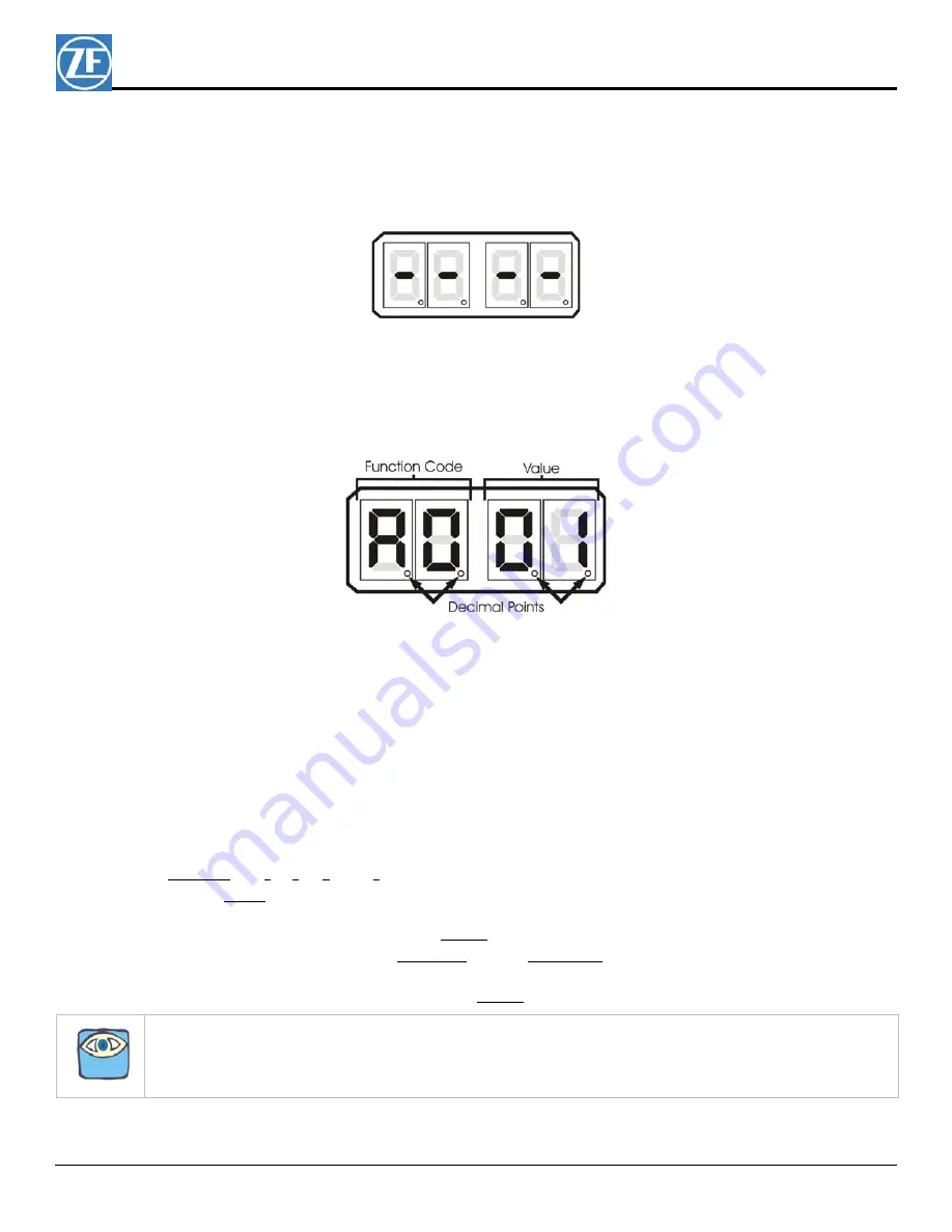
• The first two digit Display LED’s to the left, indicate the Function Code, which is alphanumeric.
Figure ENG-283-7: Display LED Designations
• The second two digit Display LED’s indicate the numeric Value that is currently programmed into
the Station Expander for the Function Code displayed to the left.
• A decimal point indicator is located on the bottom right corner of each Display LED. (Figure ENG-
283-7: Display LED Designations)
8.3
Push Buttons
There are four Push Buttons with arrows located below the Display LED on the Station Expander cover.
These push buttons are used to scroll through, select, and store the Functions and Values. The direction of
the arrow indicates “Left”, “Down”, “Up”, and “Right”. See Figure ENG-283-5: Station Expander Display
• “Up” and “Down” Push Buttons
Pressing the “Up” or “Down” Push Buttons
once
has the following functions:
• Stops Normal Operation Display (running red center dash lines) and activates the Function
Menu.
• While in the Function Menu, scrolls through the Function Codes one at a time.
• When in Set Up Mode, increases (Up) or decreases (Down) the Function Value one digit at
a time.
• When an Error Code is displayed, scrolls through the error messages one at a time.
NOTE: Refer to Troubleshooting section of the processor manual for steps to be taken for Error Messages.


