Operating Instructions
2K800/2K801/2K802
Initial
Installation
EN 4161.758.103m – 2015-10
19
If the number of resistors is rather small, also
a lower control current can be used.
The control current for end-position monitoring
is to be set according to length, line and
transition resistance and the number of
connection points. Increased resistance due to
corrosion after some time must be taken into
consideration. Switching of inductive loads by
means of the control current requires it to be
wired parallel to the load by a diode.
If the limit switches detect that a gear is no
longer securely engaged, steps such as
emergency shut-off etc. must be initiated
through the control system.
NOTE
Electromagnetic fields can falsify the limit position
monitoring currents. This can be prevented by
re-routing or shielding the line.
The shift sequence must be monitored. If
necessary, a timer should be used to cancel the
shift sequence after approx. 2 seconds if there is
no limit switch signal (S1/S2). The main spindle
motor can not be operated until this signal is
present.
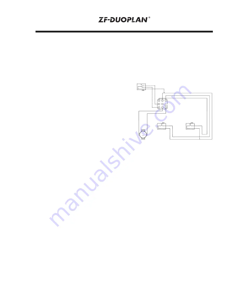
Circuit diagram for switchgear unit with solenoid
unit and two switch positions (standard) or three
switch positions (with neutral position):
1st gear ==> e. g. 4:1
2nd gear ==> 1:1
3rd gear ==> Neutral position, idling
(option)
X8
S3
S1
S2
optional
M
3
4
4
3
5
2
6
8
1
4
2
1
7
3
4
blue
blue
grey
grey
black
blue
black
black
green
The electromotive gearchange is performed by
a shift unit on the gearbox which is driven by a
DC motor (24 V DC). The gearbox shift element is
a positively locking, axially movable selector fork
that acts on a sliding sleeve.
The limit positions are monitored by limit switches
in the shift unit. The time sequence is monitored in
the control unit.
The motor must be energized when shifting from
gear 1 to 2 or vice versa. The direction of rotation
is changed over by reversing the polarity.
NOTE
Gearbox with neutral position
The neutral position can only be reached via
gear 1.
As soon as limit switch S3 receives the signal, the
DC motor must always be switched off using a
regenerative motor stop (Quickstop).
Under certain operating conditions (e. g.
installation orientation V3, higher cable resistance
values), it may be necessary to have a variable
timing element in the control unit
contact ZF.


