TROUBLESHOOTING
Page B6-2
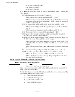
• The Command Signal at Full Ahead is 82- 84% of the Reference
Voltage when measured at the Station terminal block. The actual
value read by the Processor is 2% below that value or 80- 82% of
1023 A/D Counts (821- 841 A/D).
• The Command Signal at Full Astern is 17 - 19% of the Reference
Voltage when measured at the Station terminal block. The actual
value read by the Processor is 2% below that value or 15- 17% of
1023 A/D Counts (153- 173 A/D).
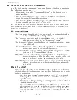
• Since the Command Signal is based on a percentage of the Refer-
ence Voltage, the distance of the Control Head from the Processor
has no impact on the performance of the system.
• The amount of voltage drop, due to current flow, is the same for
both the Reference and Command Voltages.
• The relationship between the Reference and Command Voltages
when thought of as a percentage, will remain the same regardless
of distance. For instance, here are two examples.
Example 1
Reference Voltage 5.00 VDC1023 A/D Counts
Command Voltage2.45 VDC501 A/D Counts
Example 2
Reference Voltage4.80 VDC1023 A/D Counts
Command Voltage2.35 VDC501 A/D Counts
As you can see by the examples, even though the Command Volt-
ages are different between Examples 1 and 2, the resulting A/D
counts, are the same because of the different Reference Voltages.
This would result in the Processor commanding the identical out-
puts (Clutch & Throttle) in both cases.
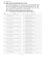
A) The A/D count for a specific Control Head’s lever can be
seen on the Processor’s Display by following the steps out-
lined in Section B4, page B4-1.
B) Once the appropriate remote station is reached, ensure that
the displayed A/D Count represents the Neutral/Idle posi-
tion (485- 505 A/D counts). Command will not be accepted
unless the Control Head’s lever is at the Neutral/Idle posi-
tion.
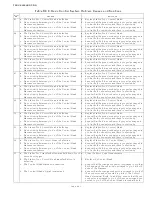
The following table shows the appropriate A/D Counts for various
Control Head lever positions:
NOTE: T
HE
A/D
VALUES
LISTED
FOR
F
ULL
A
HEAD
AND
F
ULL
A
STERN
REPRESENT
THE
POINT
WHERE
MAXIMUM
THROTTLE
IS
REACHED
. T
HE
A/D
COUNT
WHEN
THE
C
ONTROL
H
EAD
LEVER
IS
PHYSI
-
CALLY
AT
IT
’
S
MAXIMUM
POINT
WILL
BE
HIGHER
,
BUT
MAY
NOT
EXCEED
THE
OUT
-
OF
-
RANGE
VAL
-
UES
LISTED
IN
Table B6-3: Control Head Lever A/D Counts
Control Head Lever Position
A/D Count
Lever Out of Range Low
100
Full Astern
153 - 173
Neutral/ Idle
485 - 505
Summary of Contents for ClearCommand 9000 Series
Page 132: ......
Page 133: ...APPENDIX A...
Page 134: ......
Page 139: ......
Page 140: ...Page A 4...
Page 143: ......
Page 144: ...10...
Page 148: ...Page A 18...
Page 149: ...Page A 19 TEMPLATE...
Page 150: ...Page A 20...
Page 152: ...Page A 22...
Page 154: ...Page A 24...
Page 156: ...Page A 26...
Page 157: ...Page A 27 Drawing 11488D 1 Twin Screw Single APS Connection Alternate Remote Switch...
Page 158: ...Page A 28...
Page 159: ...Page A 29 Drawing 11488D 2 Twin Screw Dual APS Connections...
Page 160: ...Page A 30...
Page 161: ...Page A 31 Drawing 11488D 3 APS Notes Page...
Page 162: ...Page A 32...
Page 164: ...Page A 34...
Page 166: ...Page A 36...
Page 170: ...Page A 40...
Page 172: ...Page A 42...
Page 176: ...Page A 46...
Page 178: ...Page C 48 ZF Mathers LLC 12125 Harbour Reach Drive Suite B Mukilteo WA 98275...
Page 179: ...APPENDIX B...
Page 180: ......
Page 234: ...Appendix B 6...
Page 238: ...Appendix B 10...
Page 242: ...Appendix B 14...
Page 247: ...Service Field Test Unit Reference Manual MM13927 Rev E 4 07...
Page 248: ......
Page 250: ...Page ii Table of Contents...
Page 264: ...SERVICE FIELD TEST UNIT MM13927 RvD 10 03 Page 3 2...
Page 265: ...APPENDIX C...
Page 266: ......
Page 267: ...Appendix C 1 Drawing 12284A 1 ClearCommand Diagram all options...
Page 268: ...Appendix C 2...
Page 269: ...Appendix C 3 Drawing 12284A 2 ClearCommand Circuit Board Connections...
Page 270: ...Appendix C 4...
Page 271: ...Appendix C 5 Drawing 12284A 3 ClearCommand Drawing Notes Page...
Page 272: ...Appendix C 6...


