Page A-43
ZF Mathers, LLC
12125 Harbour Reach Drive, Suite B
Mukilteo, WA 98275 U.S.A.
800-546-5455 / 425-583-1900
Fax: 425-493-1569
MM13821 Rev.A 8/03
9000 Series Processors and Actuators
585CE Actuator (Serial Number B06500 and up)
813CE Actuator (Serial Number C01150 and up)
ClearCommand Processors (Serial Number D02100 and up)
Revisions List
This procedure is to be used in conjunction with the technical manual supplied with the Sys-
tem’s Actuator/Processor.
A) Parts Required:
One 43C Conversion Kit (P/N 13821) for each cable. Kit includes the following:
• 43C cable nut (P/N MS12820)
• 43C cable retainer (P/N 13694)
• Cable retainer screws (P/N 00791)
B) Tools Required:
• Snap Ring Tool or Small Slotted Screwdriver
• Phillips Screwdriver
• 7/16 Nut Driver or Socket
• 7/16 Open End Wrench
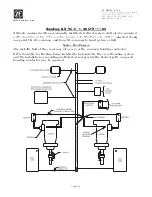
C) Actuator/Processor Preparation [Refer to Figure 1:]
D) Remove cover to Actuator/Processor.
E) Remove screws holding Cable Retainer in place.
F) Remove and discard Cable Retainer.
G) Remove the Snap Ring holding the Cable Connect Nut in the cross-bar using a snap
ring tool or small screwdriver.
H) Remove and discard Cable Connect Nut and Snap Ring.
43C Cable Conversion Kit
Rev
Date
Revision Description
A
8/03
Added 9000 Series.
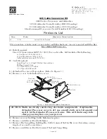
Figure 1: Actuator/Processor Preparation
CAUTION: Static electricity can destroy electronic components. Anytime the
Actuator/Processor cover is off, use an anti-static wrist strap and con-
nect it to the Actuator/Processor frame. This will drain any static
charge you may have on your person.
Cross-bar
Remove
33C Cable
Connect Nut
Lead Screw
Remove
Snap Ring
Cable Retainer
Screws
11452-
Summary of Contents for ClearCommand 9000 Series
Page 132: ......
Page 133: ...APPENDIX A...
Page 134: ......
Page 139: ......
Page 140: ...Page A 4...
Page 143: ......
Page 144: ...10...
Page 148: ...Page A 18...
Page 149: ...Page A 19 TEMPLATE...
Page 150: ...Page A 20...
Page 152: ...Page A 22...
Page 154: ...Page A 24...
Page 156: ...Page A 26...
Page 157: ...Page A 27 Drawing 11488D 1 Twin Screw Single APS Connection Alternate Remote Switch...
Page 158: ...Page A 28...
Page 159: ...Page A 29 Drawing 11488D 2 Twin Screw Dual APS Connections...
Page 160: ...Page A 30...
Page 161: ...Page A 31 Drawing 11488D 3 APS Notes Page...
Page 162: ...Page A 32...
Page 164: ...Page A 34...
Page 166: ...Page A 36...
Page 170: ...Page A 40...
Page 172: ...Page A 42...
Page 176: ...Page A 46...
Page 178: ...Page C 48 ZF Mathers LLC 12125 Harbour Reach Drive Suite B Mukilteo WA 98275...
Page 179: ...APPENDIX B...
Page 180: ......
Page 234: ...Appendix B 6...
Page 238: ...Appendix B 10...
Page 242: ...Appendix B 14...
Page 247: ...Service Field Test Unit Reference Manual MM13927 Rev E 4 07...
Page 248: ......
Page 250: ...Page ii Table of Contents...
Page 264: ...SERVICE FIELD TEST UNIT MM13927 RvD 10 03 Page 3 2...
Page 265: ...APPENDIX C...
Page 266: ......
Page 267: ...Appendix C 1 Drawing 12284A 1 ClearCommand Diagram all options...
Page 268: ...Appendix C 2...
Page 269: ...Appendix C 3 Drawing 12284A 2 ClearCommand Circuit Board Connections...
Page 270: ...Appendix C 4...
Page 271: ...Appendix C 5 Drawing 12284A 3 ClearCommand Drawing Notes Page...
Page 272: ...Appendix C 6...


