background image

Operating Instructions  

2K800/2K801/2K802  

Initial 

Installation 

23 

3.6.5


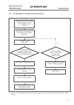
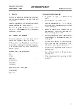
Switching logic for switching unit with servo-motor 


Reduce main spindle motor speed 

from operating speed to zero. 

Leave controller enable on  

converter. 

Apply desired oscillating speed to 

converter and speed controller 

without delay. 

1)


Servomotor for gear ratio  

change ON (pin 2 and 3) 

Gear ratio change is 

 completed within 2 seconds.  

(Acknowledgement from limit 

switch S1 or S2 from the shift unit) 

Shut off desired oscillating speed. 

Solenoid OFF after 0.5 to 1.0  

seconds 

Gear ratio change complete. 


Number of attempted 

shifts > 5 each from the 

starting position 

(polarity reversal) 

Gear ratio change not successful: 

Switch off main spindle motor. 

Check system. 

Start main spindle motor


1)   Alternatively, the first switching test can be performed without oscillating, but this requires a de-energized main spindle motor or minor output-

end masses. 

Summary of Contents for 2K800

Page 1: ...OPERATING INSTRUCTIONS Two speed Gearbox 2K800 2K801 2K802 10 2006 Edition 4161 758 103g ...

Page 2: ...nstructions also apply to the predecessor model 2K50 Subject to alterations in design Copyright by ZF Reproduction in whole or in part is only allowed with our written approval and authorization Printed in Germany Edition 10 2006 4161 758 103g ...

Page 3: ... Open design with adapter ring for 2K802 15 3 4 Gearbox fit 16 3 5 Output 17 3 5 1 Version with belt output 17 3 5 2 Version with coaxial output 17 3 6 Electrical connection gearchange 17 3 6 1 Switching unit with solenoid unit 17 3 6 2 Switching unit with servo motor 19 3 6 3 Switching logic for switching unit with solenoid unit 21 3 6 4 Switching logic for switching unit with solenoid unit and c...

Page 4: ...perating Instructions Contents 2K800 2K801 2K802 4 5 Maintenance 32 5 1 Oil change 32 6 Repair 33 6 1 Gearbox fault checklist 33 6 2 Gearbox disassemble 34 6 3 Hub 34 7 Frequently Asked Questions FAQ 35 ...

Page 5: ...epairing ZF units are responsible for their own work safety Every applicable safety regulation and legal requirement must be complied with in order to prevent injury to personnel and or damage to the product during the course of maintenance and repair work Repair staff should familiarize themselves with these regulations before commencing work Correct and proper repair of these ZF products can onl...

Page 6: ...se Remarks Grease Shell Avania WR2 Fuchs Renolit CXEP2 Esso Beacon EP2 General purpose Gearbox oil HLP 46 to ISO VG 46 Gearbox oil for recirculating lubrication Can also be used for recirculating lubrication with heat exchanger Gearbox oil HLP 32 to ISO VG 32 Gearbox oil for recirculating lubrication with heat exchanger ...

Page 7: ...ed reduction is required The gearboxes have coaxial output and are suit able for the high speeds generated in machine tool construction 2 2 Features Two speed gearboxes for AC and DC main spindle drives in machine tools Compact thanks to planetary design Flange mountable to all AC DC and standard motors High running smoothness and low noise operation thanks to helical gearing Low torsional backlas...

Page 8: ...ate 2 with radial shaft seal 3 and hub bearings 4 as necessary Housing Gearbox housing 5 Input Sun gear 6 Ring gear 7 Ring gear bearings 8 Output Bearing housing 9 Output bearings 10 11 Output shaft 12 Radial shaft seal 13 Planet carrier 14 Axial bearing 15 Shift mechanism Sliding sleeve 16 Shift fork 17 Brake disc 18 Shift unit With servo motor or solenoid unit 19 027933 ...

Page 9: ...ble output torques Braking times must be adapted accordingly Standard fixing dimension in mm in accordance with EN 50347 2001 Two speed gearbox 2K800 FF350 2K801 FF400 2K802 FF500 Motor size 180 200 225 h 180 200 225 d 60 65 75 l 140 0 2 140 0 2 140 0 2 b 300 350 450 e2 350 400 500 a1 400 450 550 s2 4x18 5 8x18 5 8x18 5 Type 2K800 2K801 802 Standard version 2K800 2K801 802 with STW i 1 236 Nominal...

Page 10: ...on and Design 2K800 2K801 2K802 10 2 5 Installation positions Horizontal B5 Horizontal B5 shift unit rotated Vertical V1 Vertical V3 CAUTION The breather outlet must always be at the top regardless of the installation position 027929 ...

Page 11: ...63 0 200 A B C L 140 2K802 0 030 0 063 0 063 0 200 Tolerances A B C to DIN 42955R Please note that the tolerance of the shaft length L is restricted in relation to the DIN standard CAUTION The special tolerance for shaft length L must be maintained in order to guarantee fault free gearbox operation Undersize shafts must be compensated for by using shims when mount ing to the motor Oversize shafts ...

Page 12: ...h 2K800 2K801 2K802 60 mm 65 mm 75 mm 80 mm A18x11 A18x11 A20x12 A22x14 110 mm 110 mm 125 mm 140 mm 3 2 1 Semi key balancing In semi key balancing the keyway is filled with a balance compensation corresponding to approxi mately half a key shape B by default This is based on the original key shape length and posi tion used by the motor manufacturer and is de fined as a counterweight In semi key bal...

Page 13: ...ese enable balancing of the motor shaft length tolerances and therefore compliance with reference dimension C 3 3 1 Open design The open version is the gearbox without adapter plate but with seal on the motor output shaft 2 to prevent gearbox oil ingress The drive hub 1 is delivered loose with the gear box Clean the fitting surfaces of the motor 3 and drive hub Check the motor shaft for axial and ...

Page 14: ...e the adapter plate with radial shaft seal 7 onto the motor housing Heat the drive hub to approx 120 C from the opening and slide it onto the motor shaft until it reaches the stop Then check reference dimension C and change using shims if necessary CAUTION Risk of motor shaft damage if the hub is not sufficiently heated Tighten the threaded pin 9 and secure it to pre vent it from turning see secti...

Page 15: ... reference dimension C and change using shims if necessary CAUTION Risk of motor shaft damage if the hub is not sufficiently heated Tighten the threaded pin 9 and secure it to pre vent it from turning see section 3 4 3 3 4 Open design with adapter ring for 2K802 The adapter ring allows adaptation to different connection dimensions A seal is required on the motor output shaft The adapter ring 5 and...

Page 16: ...hen doing this NOTE The external spline of the sun gear must be guided into the internal spline of the hub This can be made easier by turning to the left or right at the gearbox output The gearbox housing adapter ring if applicable and motor are bolted together using four six or eight hexagon bolts 11 Fill the gearbox with oil and connect up the recir culating lubrication system and the power supp...

Page 17: ...ns 3 6 Electrical connection gearchange The gearbox is electrically connected using the supplied 8 pole Harting connector HAN 8 U The plug in connection is located on the shift unit 3 6 1 Switching unit with solenoid unit Technical data Power rating Standard 120 W with neutral position 144 W Supply voltage 24 V DC 10 Current consumption Standard 5 A with neutral position 6 0 A The required cable l...

Page 18: ...o be wired parallel to the load by a diode If the limit switches detect that a gear is no longer securely engaged steps such as emer gency shut off etc must be initiated through the control system NOTE Electromagnetic fields can falsify the limit posi tion monitoring currents This can be prevented by re routing or shielding the line The shift sequence must be monitored If neces sary a timer should...

Page 19: ... solenoid unit The gear switching components axial movement toothed sliding collar are positive locking com ponents The switching positions are monitored by stop switches inside the switching unit A time relay has been provided for monitoring the time lapse that if necessary will reset the process if the switching process has not been completed within 2 seconds after the switching process started ...

Page 20: ...ith three switch positions with neutral position 1st Gear e g 4 1 2nd Gear 1 1 3rd Gear neutral switch position idle running option The gearing is connected up electrically using the 8 pin Harting plug HAN 8 U supplied by us The plug connection is on the switching unit with neutral position 027931 027932 ...

Page 21: ... completed within 2 seconds Acknowledgement from limit switch S1 or S2 from the shift unit Shut off desired oscillating speed Solenoid OFF after 0 5 to 1 0 seconds Gear ratio change complete Number of attempted shifts 5 each from the starting position polarity reversal Gear ratio change not successful Switch off main spindle motor Check system N N Y Y Main spindle motor start after min 0 5 seconds...

Page 22: ...S3 in the switching unit Shut off desired oscillating speed Solenoid OFF after 0 5 to 1 0 seconds Gear ratio change complete Number of attempted shifts 5 each from the starting position polarity reversal Gear ratio change not successful Switch off main spindle motor Check system N N Y Y Main spindle motor start after min 0 5 seconds 1 Alternatively the first switching test can be performed without...

Page 23: ...ear ratio change is completed within 2 seconds Acknowledgement from limit switch S1 or S2 from the shift unit Shut off desired oscillating speed Solenoid OFF after 0 5 to 1 0 seconds Gear ratio change complete Number of attempted shifts 5 each from the starting position polarity reversal Gear ratio change not successful Switch off main spindle motor Check system N N Y Y Start main spindle motor 1 ...

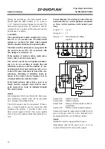
Page 24: ...r without delay 1 Servomotor for gear ratio change ON pin 2 and 3 Gearing level switching is termi nated in the neutral position by a ready signal from S3 servo motor short circuit Shut off desired oscillating speed Gearing level switching is termi nated in the neutral position Centre position is polled via Pins 5 and 7 Number of switching attempts 5 for the given output length polarity reversal G...

Page 25: ...quire a very low operating temperature level which can be reached by con necting an adapted gearbox oil supply with oil cooling The respective gearbox versions are pre pared accordingly The gearbox has different ports and connections for recirculating lubrication depending on the installation position and the operating type in order to ensure optimum gearbox cooling without affecting lubrication T...

Page 26: ... be at least ten times the recirculating oil quantity in order to ensure effec tive oil cooling NOTE To prevent gearbox damage due to lack of oil ZF recommends you install an oil level sensor at the intermediate tank A 60 µm filter must be used at the gearbox oil inlet Installation example B5 Option Tank with larger volume see chap 3 7 4 027930 ...

Page 27: ...x pressure Oil return port B5 M 0 5 l min K 2 5 l min 3 bar 5 bar G and F or D V1 M 0 5 l min K 2 5 l min 3 bar 5 bar D and E or L with suction V3 M 0 5 l min K 2 5 l min or M 0 5 l min P 2 5 l min 3 bar 5 bar 3 bar 5 bar H and I with suction or G and F NOTE The principal factor in determining the oil supply volume is always the volume that flows out of the oil return ...

Page 28: ... C when integrated and executed Cable length approx 1 000 mm Hydraulics Supply volume 1 21 cm U Nominal pressure 6 5 bar Intake filter Filter mesh 100 µm Option Tank with larger volume 19 Ltr The plastic container on the pump must be removed when the tank is used The pump is then inserted together with the O ring in the appropriate opening and secured by means of M8x35 cap screws More information ...

Page 29: ...emperature monitoring PE Protective conductor Connections 11 and 12 are for monitoring the temperature of the pump motor 3 7 3 3 Connection for nominal voltage 200 240 V AC Terminal diagram 200 240 V AC Circuit diagram for 200 240 V AC Termi nal L N PE Jumpers Capacitor CB U1 U2 U5 U6 Z1 Z2 11 12 Temperature monitoring PE Protective conductor Connections 11 and 12 are for monitoring the temperatur...

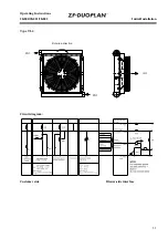
Page 30: ...the marking on the housing note suction direction The air oil heat exchanger can be supplied in two rat ing classes TL 1 and TL 4 Technical data Nominal voltage 24 V DC Power consumption TL 1 41 W TL 4 113 W Blower drive brushless NOTE The oil coming out of the heat exchanger must always be above the oil coming in The oil through flow direction can be as required AIR Oil Oil Rotation direction Typ...

Page 31: ...Operating Instructions 2K800 2K801 2K802 Initial Installation 31 Type TL 4 Circuit diagram Customer side Blower side interface Oil Oil Air Rotation direction ...

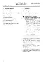
Page 32: ...ned from your local environmental protection authority and follow any instructions herein at all times Always collect used oil in a suitably large container Always dispose of used oil clogged fil ters lubricants and cleaning agents in accordance with environmental pro tection laws Always observe manufacturer in structions when dealing with lubri cants and cleaning agents Drain used gearbox oil int...

Page 33: ...Gearbox data on the model plate Typ Type Stückliste Parts list no Serien Nr Serial no Motor data on the model plate Manufacturer Type size Questions for fault diagnosis Is gearbox oil sight glass dark discolored black Smell of burning oil at oil breather Gearbox running noise in 1 1 or 4 1 gear ra tio or only in one rotation direction or in both rotation directions Before the running noise occurre...

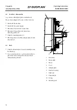
Page 34: ...nnections Disconnect the gearbox oil connections drain the gearbox oil Undo the mounting bolts 11 Pull the gearbox 6 off the adapter plate 5 and drive hub 1 6 3 Hub Undo the threaded pin 9 used to radially secure the fitted key Use a removing device e g three arm puller to pull off the drive hub against the motor shaft without heating the hub 1 Drive hub 2 Motor shaft 3 Motor 4 Cover 5 Adapter pla...

Page 35: ...e normalizes after several gear changes Gearbox is loud running noise in ratio Motor shaft is too long axial bearing damaged Check bearing install new bearing if necessary Gearbox leaking at gearbox input output Defective seals Renew seals send gearbox to ZF for inspection if necessary Gearbox leaking at breather Oil has aged Too much oil added during oil change Change the oil Check the oil level ...

Page 36: ...Frequently Operating Instructions Asked Questions FAQ 2K800 2K801 2K802 36 ...

Page 37: ...ZF Friedrichshafen AG Sonder Antriebstechnik Ehlersstraße 50 D 88046 Friedrichshafen Phone 49 75 41 77 0 Fax 49 75 41 77 34 70 E mail ZFM Sales zf com Internet www zf com ...

Reviews: