


CAN Bus Wiring
The EVMS Core has two CAN bus ports (5-pin aviation plugs) on one side of the case. These
are wired identically, and can be connected in either order in any location along the CAN
bus. The EVMS Monitor and BMS12 modules use 5-pin Molex C-Grid SL series plugs for
CAN bus connections. Wiring is shown in the diagrams below:
Shield
CAN L
CAN H
Gnd
12V
Shield
CAN L
CAN H
Gnd
12V
CAN pin assignments
as viewed on EVMS Core
CAN pin assignments
as viewed on EVMS Monitor
CAN buses work best when wired as a single daisy chain of devices, with 120ohm termination
resistors at each end to prevent signal reflection. Most ZEVA CAN-enabled devices have dual
CAN ports for easy daisy-chaining. The order of devices is unimportant - usually the shortest
path between devices is best.
The EVMS Monitor is most commonly installed at one end of the CAN bus so only has a
single CAN port, and a built-in internal termination resistor. The monitor may be installed
in the middle of a CAN bus by creating a short Y-branch off the bus to the Monitor’s CAN
plug, and removing the small pin jumper beside the plug to disable the internal termination
resistor.
For the sake of noise immunity, CAN buses typically use twisted pair cable. Since electric
vehicles can involve high electromagnetic interference (EMI) from the traction circuit, we
recommend using shielded twisted pair wire for maximum noise immunity. Very short
connections are usually OK with untwisted and/or unshielded cable.
CAN buses draw a significant amount of power (the full EVMS and BMS will be using in the
order of a few hundred milliamps) so in order to reduce quiescent drain on the auxiliary
battery, the EVMS Core will power down the CAN bus after 1 minute in Idle state (neither
driving, charging, or in Setup). Setup mode can only be entered from Idle state, so this one
minute window will give plenty of time to enter. The Core will also provide 1 minute of CAN
power after powering up.
If the outputs are disabled due to a BMS error (such as an over-voltage or under-voltage
cell), the CAN bus will remain powered up for 1 hour. This is to allow a window for the BMS
modules to continue pack balancing after the charger has been shut down, before the CAN
bus is powered down to avoid flattening the auxiliary battery.
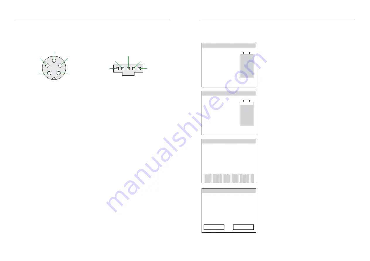
EVMS Monitor
The EVMS Monitor is used to remotely interact with other devices on the CAN bus, both
for viewing operating data and to edit settings. The Monitor has various different pages of
information as described below.
EVMS: Idle
Voltage
Current
Power
Temp Aux V Charge
- 13.0V 100%
–
–
–
The default display when the vehicle is idle (neither
driving nor charging). Battery state of charge and
auxiliary battery voltage are visible, but other
parameters are only available while driving or
charging.
EVMS: Running
Voltage
Current
Power
Temp Aux V Charge
23˚C 13.5V 90%
148V
42A
6.2kW
The standard display when Precharging, Running or
Charging, showing instantaneous voltage, current,
power, temperature, auxiliary battery voltage and
traction battery State of Charge.
Touching the left or right half of the display will swap
to the previous or next display page respectively.
BMS Summary: 45 cells
Avg voltage Balance
Min voltage Max voltage
M0 C4 M2 C8
3.32V 90%
3.31V 3.33V
BMS summary page, showing the total number of cells
being monitored, the voltage and location of both the
lowest and highest cells, the average voltage per cell,
and a metric for pack balance.
Along the bottom is a bar graph showing all cells being
monitored. Green bars indicate cells within range. Bars
will change to blue for undervoltage cells, orange for
cells being balanced, and red for overvoltage cells.
BMS Details: Module 1
Cell voltages
3.32V 3.33V 3.32V 3.31V
3.33V 3.31V 3.32V 3.32V
3.31V 3.32V 3.33V 3.32V
3.32V 3.32V 3.33V 3.31V
Temp1: 23˚C Temp2: 25˚C
Prev Next
Detailed information for a single BMS module,
showing voltage of each cell (to 2 decimal places) and
two temperatures if available. Orange bars beneath
the voltages indicate if cell shunts are currently on.
Touch within the Prev and Next buttons to change
which BMS module is being viewed, or anywhere else
in the display to change Monitor pages.


