ZERO EMISSION VEHICLES AUSTRALIA
4-12 CELL LITHIUM BATTERY MANAGEMENT SYSTEM
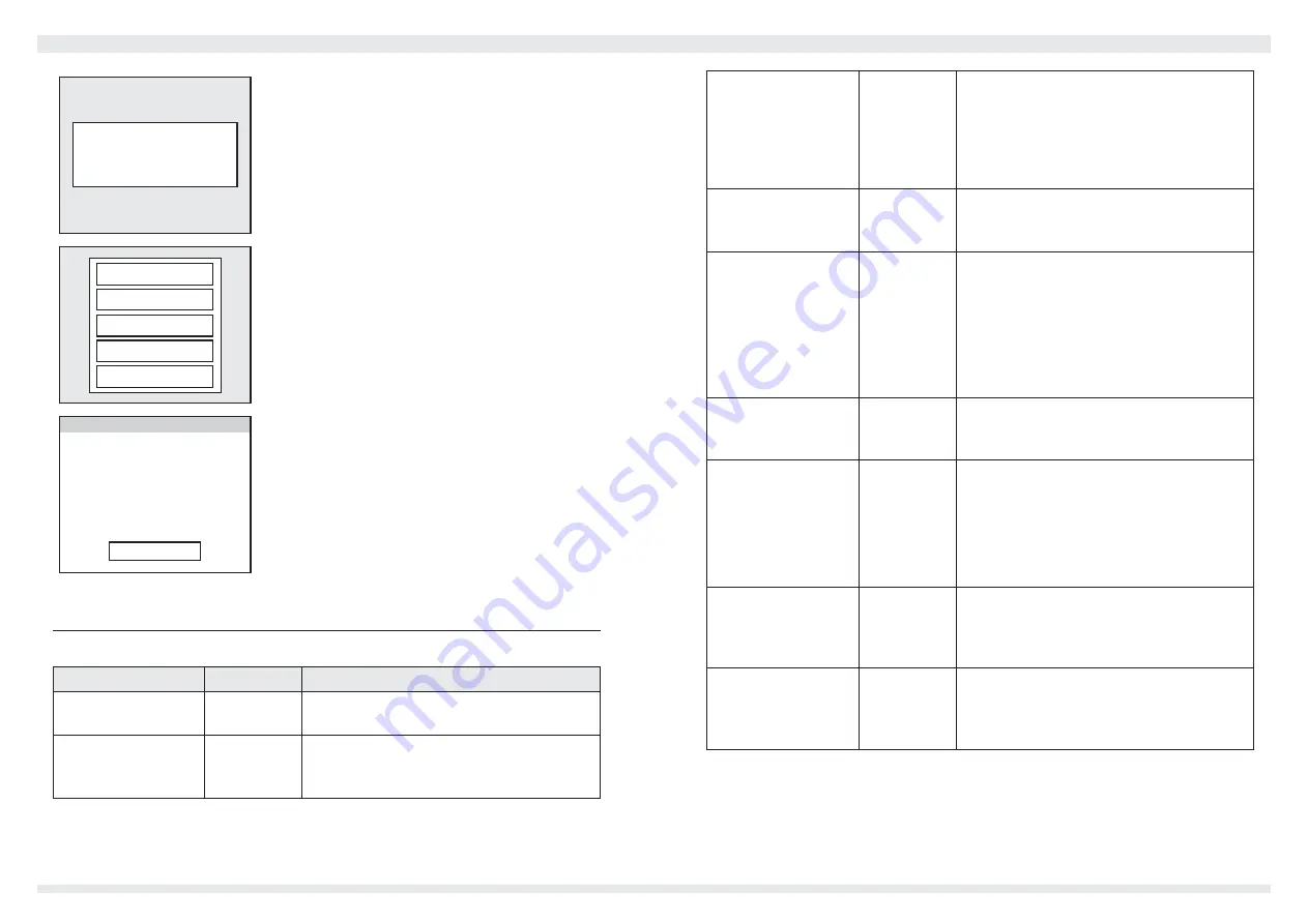
Warning:
Overcurrent shutdown
If the BMS detects an error, this warning page
will be displayed. In most cases, the error can be
acknowledged/reset by tapping the screen.
Enter Setup
Reset SoC
Zero Current
Power Off
Exit Options
You can bring up the options menu by touching and
holding for 1 second. From here you can do a manual
reset of the State of Charge (back to 100%), enter the
Setup mode, switch the display off, or command the
BMS12i to turn off.
ZEVA BMS: Setup
Parameter:
Pack capacity
Value:
100Ah
Exit Setup
<
<
>
>
If you choose Enter Setup, the Monitor can be used to
modify settings for the BMS12i. The top row selects the
parameter, and the bottom row adjusts the value, in
both cases by touching the left or right arrows on each
side. Once finished, touch Exit Setup and the new
parameters will be transmitted to the BMS12i.
List of Settings
The following table describes the parameters available in the Settings page.
Name
Range
Description
Pack capacity
5-1200Ah
The rated capacity of your traction battery pack,
in Amp-Hours.
SoC warning
0-100%
The BMS12i can raise a warning when the
battery’s State of Charge reaches a predetermined
minimum level. (Use 0% to disable.)
Full voltage
1-70V
The BMS uses a “full voltage” threshold
(combined with low charge current) to detect
charge completion and automatically re-
synchronize the SoC to 100% when pack
voltage exceeds this value. Typically set value to
just below your peak charge voltage.
Warn current
0-1200A
The BMS12i will provide a warning if the current
in or out of the battery exceeds this threshold.
Set to 1210A to disable (will display as “off”).
Trip current
0-1200A
The BMS12i will automatically shut down the
battery pack if current exceeds this threshold
(for over 1 second continuously). Note: This
should not replace a physical fuse, but can be
used as a “first line of defence”.
This is considered a serious error which will
require the device to be power cycled to reset.
Num cells
4-12
The number of cells the BMS should expect to
see in the battery pack. Warning: If this is set
incorrectly, some cells may not be monitored.
Shunt size
None, 100,
200 or 500A
Selects the size of current shunt connected to
the BMS’s shunt interface terminals, for correct
current scaling. (75mV shunts only.)
This should be set to “None” if you have no
shunt connected, or are using an external
current sensor on the CAN bus.
Min voltage
1.50-4.00V
The minimum voltage any single cell should
be allowed to reach. If any cell goes below
this threshold, the LV output relay will go open
circuit.
Max voltage
2.00-4.50V
The maximum voltage any single cell should
be allowed to reach. If any cell goes above this
threshold, the HV output relay will go open
circuit.
7
8


