26
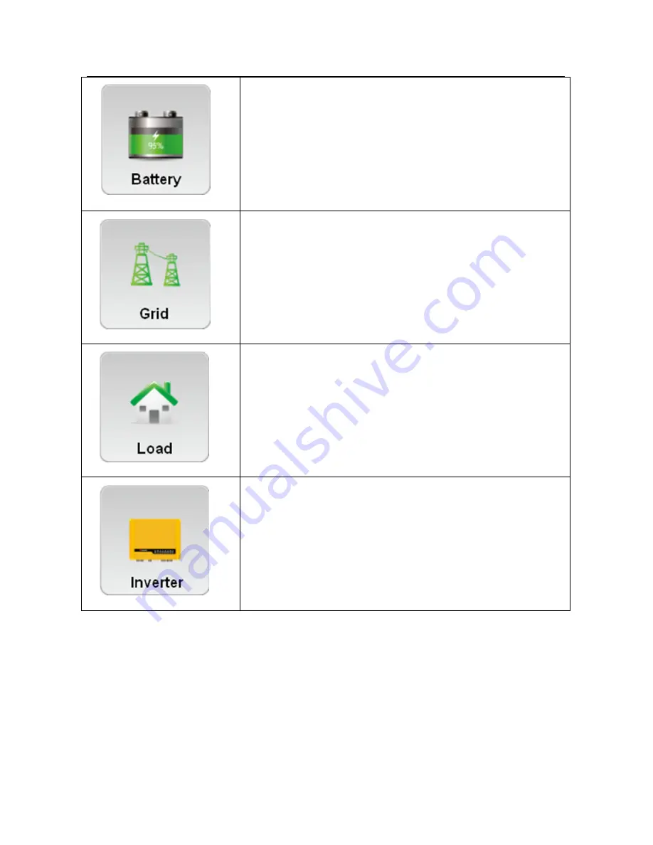
Check battery parameters
Check grid parameters
Check load parameters
Check inverter parameters
Page 1: ...Zeus Appollo Z21 Series Hybrid Inverter Installation Manual...
Page 2: ...9 4 2 PV Connection 11 4 3 Battery Connection 13 4 4 RS485 Connection 15 4 5 EzMeter Connection 16 4 6 EzConverter Connection optional 17 4 7 WiFi Connection 20 4 8 WiFi Reset Reload 20 4 9 USB Conne...
Page 3: ...ed loads the system automatically draws power from the batteries if they are charged and available If the battery capacity is insufficient to meet consumption requirements power will be automatically...
Page 4: ...observe a warning indicated in this manual may result in injury Danger of high voltage and electric shock Danger of hot surface Product should not be disposed as household waste This side up the packa...
Page 5: ...nal as instructed in this manual touching or changing components without authorization may cause injury to people damage to inverters and may void the warranty Static electricity may damage electronic...
Page 6: ...of the inverter when undertaking maintenance Do NOT insert or extract the AC and DC terminals when the inverter is in operation Electrical installation maintenance shall be conducted by a licensed el...
Page 7: ...screw x2 3 2 Product Overview Figure 3 2 1 1 Battery input ports 2 PV input ports 3 DC switch optional 4 Wireless port 5 USB port 6 RS485 ports 7 AC output ports 1 2 3 4 6 7 5 3 3 Selecting The Mounti...
Page 8: ...tenance activities please install the inverter at eye level Inverters should NOT be installed near flammable and explosive items Any strong electro magnetic equipment should be kept away from the inst...
Page 9: ...nverter is heavy Please be careful when removing from the packaging 1 Use the wall mounted bracket as a template and drill 6 holes on the wall 10 mm in diameter and 80 mm in depth Refer to Figure 3 4...
Page 10: ...d the load please install a separate AC breaker 250VAC 30A between the inverter and the grid This will ensure that the inverter can be securely disconnected during maintenance It s very important for...
Page 11: ...r and the grid 4 Disconnect the screw cap from the insulator 5 Disconnect the waterproof ring from the insulator 6 Feed the cable through the components in this order screw cap waterproof ring insulat...
Page 12: ...polarity Incorrect polarity could permanently damage the inverter Check the short circuit current of the PV string The total short circuit current must not exceed the inverter s maximum PV current Th...
Page 13: ...ere is a risk of electrical shock if the total minimum resistance requirement is not met There are two types of PV plugs SUNCLIX series and MC4 series Refer to Figure 4 2 1 Figure 4 2 1 SUNCLIX series...
Page 14: ...s It is a normal phenomenon that an electric arc occurs when connecting a battery to the inverter without the use of a DC breaker It s very important for system safety and efficient operation to use a...
Page 15: ...een the inverter and the battery 3 Disconnect the screw cap from the insulator 4 Disconnect the waterproof ring from the insulator 5 Feed the cable through the components in this order screw cap water...
Page 16: ...efer to chapter 4 5 chapter 4 6 Please follow the steps below to implement the RS485 connection on the inverter side 1 Remove the RS485 waterproof assembly from the inverter 2 Disconnect the screw cap...
Page 17: ...RX_RS485A TX_RS485B TX_RS485A Function Color orange white orange green white blue blue white green brown white brown RS485 waterproof assembly RESERVED RESERVED RESERVED 4 5 EzMeter Connection The Ez...
Page 18: ...oad PIN 1 2 3 4 5 6 7 8 RESERVED RX_RS485B RX_RS485A TX_RS485B TX_RS485A Function Color orange white orange green white blue blue white green brown white brown RESERVED RESERVED RESERVED Connection il...
Page 19: ...ser manual 1 Lithium battery communication connects to an EzConverter via RS485 interface if the protocol is RS485 Refer to Figure 4 6 1 2 Lithium battery communication connects to an EzConverter via...
Page 20: ...n RESERVED RESERVED RESERVED T568B RS232 Figure 4 6 3 Battery Li Ion PIN 1 2 3 4 5 6 7 8 RESERVED RX_RS485B RX_RS485A TX_RS485B TX_RS485A Function Color orange white orange green white blue blue white...
Page 21: ...Reload The WiFi reload function is used to change the WiFi configuration to a default value Please reset the WiFi according to the WiFi configuration illustration after using the function 1 Hold the...
Page 22: ...ement a USB connection Figure 4 9 1 open USB cover insert USB data cable 5 LED Lights Illustration Inverter Status LED Color Inverter Status Note LED Display Status Wifi Yellow WiFi Reset or Reload OK...
Page 23: ...The Z21 series inverter has no LCD screen it can be controlled via a mobile device with the APP software Z21Manage 6 1 Download and Install Go to Google play Search for Z21Manage in Google Play downlo...
Page 24: ...you can choose the SSID of the WiFi router and join it If you have any questions please refer to the WiFi fast installation sheet 6 2 2 Select Safety country Country for Safety Setting Attention Afte...
Page 25: ...you can skip the next step because the Zeus Appollo Solar Hybrid Inverter will automatically control the battery charging and discharging based on demand Battery Charging and Discharging Grid Charge T...
Page 26: ...e associated with PV panels PV Charge Without Grid When the switch is on the PV panels can charge the battery without the grid connected This function allows the system to be set off grid Back up Func...
Page 27: ...26 Check battery parameters Check grid parameters Check load parameters Check inverter parameters...
Page 28: ...ame and the password when you creating the solar station There are three historical data display formats Year Month and Day Defaulted as Year Click Query for selection Check the battery level Please e...
Page 29: ...s have the following main operating modes providing for different conditions Mode 1 Energy produced by the PV system is first used for the local load the excess energy is then used for charging batter...
Page 30: ...o PV panels battery energy is used for the local load first the grid also can supply power when the battery capacity is insufficient Mode 3 If the grid is faulty or there is no grid the system can sti...
Page 31: ...30 batteries supply energy for the local load Connected to Emergency Backup Output only Mode 4 The battery can be charged by the grid charging time and power can be set up adaptably...
Page 32: ...ure Relay self checking failure DC Injection High Too high DC injection EEPROM R W Failure Memory chip failure SPI Failure Internal communication failure DC Bus High Too high BUS voltage AC HCT Failur...
Page 33: ...g voltage V 125 Max DC current A 15 15 No of DC connectors 2 No of MPPTs 2 can parallel DC connector SUNCLIX MC4 Optional Battery Battery Type Lead acid or Li Ion Lead acid or Li Ion Battery voltage r...
Page 34: ...monitoring unit Integrated Anti islanding protection Integrated DC switch PV Integrated AC over current protection Integrated Insulation monitoring Integrated Certifications Standards Grid regulation...
Page 35: ...34 Standby losses W 8 Cooling Natural convection Noise emission dB 25 Display LED light APP Communication USB2 0 or WiFi Standard warranty years 5 10 15 20 25 optional 11 Certificates...