---------------------------------------------------------------------------------------------------------------------------------------------------------
6
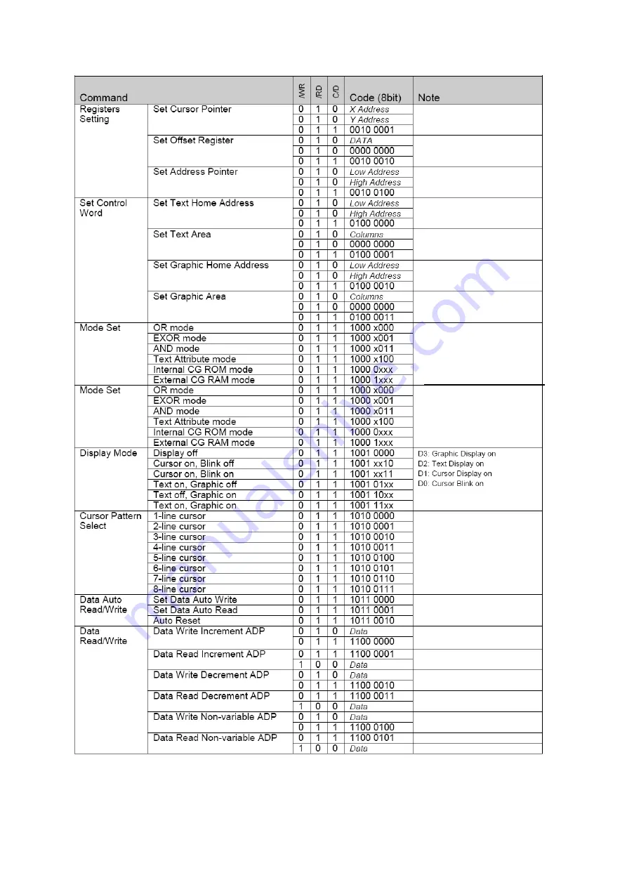
Display Control Instructions(continue)
Page 1: ...ng Angie 6 O clock direction 8080 serial 8 Bit MPU Interface Backlight LED Operating Temperature Range 20 to 70 Storage Temperature Range 30 to 80 Note Color tone is slightly changed by temperature an...
Page 2: ...2 3 EXTERNAL DIMENSIONS 4 BLOCK DIAGRAM 5 POWER SUPPLY 6 PIN DESCRIPTION ITEM SYMBOL LEVEL FUNCTION 1 FG Frame Ground 2 VSS 0V Power Ground 3 VDD 5 0V Power Supply For Logic...
Page 3: ...Storage Temperature Tst 30 80 Note Voltage greater than above may damage the module All voltages are specified relative to VSS 0V 8 ELECTRICAL CHARACTERISTICS 8 1 DC Characteristics VDD 5V VSS 0V Ta 0...
Page 4: ...0 nS Access time tACC 150 nS Output hold time tOH 10 50 nS MPU write timing 9 FUNCTION SPECIFICATIONS 9 1 Adjusting The LCD Display Contrast A Variable Resistor must be connected to the LCD module for...
Page 5: ...using RST terminal When turning on the power supply maintain RST terminal at low level After the power supply stabilized released the reset terminal RST H Items Symbol Min TYP Max Unit Reset time tr 1...
Page 6: ...6 Display Control Instructions continue...
Page 7: ...the LCD with Isopropyl Alcohol or Ethyl Alcohol Other solvents eg water may damage the LCD 10 5 When mounting the LCD module make sure that it is free form twisting warping and distortion 10 6 Ensure...
Page 8: ...apply signal to the LCD module without power supply 10 15 IC chip eg TAB or COG is sensitive to the light Strong lighting environment could possibly cause malfunction Light sealing structure casing is...