background image

Gear shifting

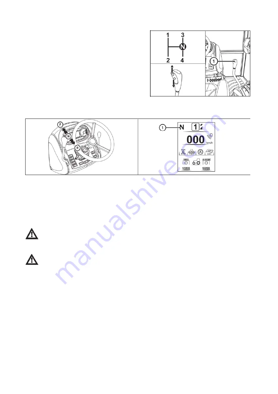
Reversing lever

PGPPN184

Reversing lever selects direction of movements of the tractor (forward, backward).

F -

 travel forward (16 speeds) 

R -

 travel backward (16 speeds)

The reversing gearbox includes 16 reverse speeds that are approximately the same as the forward speeds. 

Therefore consider carefully when shifting a reverse gear for the given character of your work.

Perform reverse shifting with clutch pedal depressed and tractor in standstill.

The lever neutral position is indicated by the symbol 

N

 (1) on the instrument panel display.

When shifting individual gear speed (1-4) or reversing (F-R) observe the instructions for 

putting the tractor in motion and gear shifting in this manual. When the tractor has been started and 

is still standing, depress the clutch pedal and wait for approx. 2 seconds. Only then shift the required 

gear speed or select the reverse direction. 

To increase safety and to avoid unexpected situations use the foot brake during the shifting as well.

The tractors are equipped with a four-speed synchronized 
transmission, a two-speed torque multiplier, a reverser 

and a two-speed reduction. 

The four-speed transmission is operated by the main 

gearshift lever (1) with buttons for the torque multiplier 

control. 
The gearshift scheme is located on the gearshift knob 

label and on the sticker on the right bottom windshield. 

Reverse gear can only be shifted using the reverse shift 

lever.

PGPPN018

OPERATION

82

Summary of Contents for Proxima GP Series

Page 1: ...OPERATOR S MANUAL PROXIMA GP 01 2019 Tractor is Zetor Since 1946 80 90 100 110...

Page 2: ...and get a perfect overview of how to use the tractor with maximum efficiency during various kinds of work If you observe the rules of tractor operation and maintenance and driving safety your new trac...

Page 3: ...2...

Page 4: ...9 Windshield washer tank 30 Washer nozzle 30 The liquid reservoir for control of the clutch 30 Trailer brakes 30 Hydrostatic steering 31 Air cleaner 31 Cab filtration 31 Hitches 31 Inspection of fouli...

Page 5: ...ument panel 55 Instrument panel signal lamps 55 Instrument panel instruments 56 Instrument panel buttons 56 Display description 57 Display change of display 58 Display display of air pressure in the a...

Page 6: ...lers 88 Connection of the ABS system of the trailer or semi trailer 88 The button for temporary deactivation of brakes of the trailer or semi trailer 88 Warning indication of air pressure drop 89 Air...

Page 7: ...4 Switching on the rear PTO shaft dependent revolutions 114 Front PTO shaft 115 Activation of the front PTO shaft common working mode 115 Activation of the front PTO shaft stationary working mode 116...

Page 8: ...ving with agricultural machines attached to the front three point hitch 149 Wheel tread change 151 Change of front wheels track with front drive axle 151 Gauges of the front wheels of the front drive...

Page 9: ...ies 176 Oil for the front driving axle 176 Oil for the hydrostatic steering of the tractors 177 Front PTO oil 177 Plastic lubricant for the tractor 177 A C coolant 178 Liquid for the cooling system of...

Page 10: ...le filter maintenance 198 Adjustment 199 Cogged belt tension 199 Bleeding of tractor brake system 200 Check and adjustment of service and parking brakes 200 Service brake adjustment 201 Parking brake...

Page 11: ...10...

Page 12: ...mber 4 Tractor serial number When ordering spare parts and within all written and oral communication always specify the data of your tractor that should be written in the frames below Tractor type Tra...

Page 13: ...The right left front and back indications refer to the driving direction of the tractor PCL18N002 LOCATION OF SERIAL NUMBERS 12...

Page 14: ...ticularly careful in these situations This symbol is used to indicate the parts of the instructions for use related to the environmental protection Or the parts describing handling of hazardous wastes...

Page 15: ...rking position Diesel particulate filter regeneration disable inhibit Lower working position Transmission failure Fast rock lower Transmission oil filter Rock damping Brakes failure Rockshaft raise Pa...

Page 16: ...Windscreen wiper intermittent Hourmeter Windscreen washer and wiper Total distance covered Rear window wiper Distance covered by the tractor since the last reset of the value Rear window heating Area...

Page 17: ...switch Seat adjustment longitudinal fore and aft Seat adjustment seatback recline Bottom seat cushion Longitudinal adjustment controller Seat turning controller Seat tilt controller SAFETY INSTRUCTION...

Page 18: ...boots gloves goggles etc Starting the engine z Only start the engine from the driver s seat with the clutch pedal fully depressed Life hazard when starting by means of short circuiting the starter te...

Page 19: ...lability 12 with tractors with front drive axle z Respect the total permissible weight of the tractor and trailer specified on the data plate of the tractor or on the rear wheel mudguard z Do not use...

Page 20: ...fied in the technical certificate of the tractor z Persons that are not authorized to work with the attached implement must not stand between the tractor and the hitched machine implement z Before put...

Page 21: ...e tractor z At tractor equipped with reversor gear shift the reversor lever into forward drive position With stopped engine only z All work connected with refuelling cleaning lubricating and adjusting...

Page 22: ...f work or before a meal you should wash yourself with a mild agent and treat your hands with a suitable ointment or cream z When connecting and disconnection quick couplers of the hydraulic circuits u...

Page 23: ...ation connection of other electric appliances are permissible due to its possible overloading z The values of the electric installation are Nominal voltage 12 V Grounded minus pole pole z Using starti...

Page 24: ...rbidden Using the seat for front passenger during the work with a tractor e g during the work on the fields is explicitly forbidden The use of safety belt on front passenger s seat is governed by vali...

Page 25: ...tractor in accordance with the EU Directive 2018 985 Resulting noise levels for the driver s hearing in accordance with the European directive EU Regulation 1322 2014 Annex XIII as amended by 2018 830...

Page 26: ...It is necessary to observe applicable local valid regulations in countries which are not part of the European Union Two types of cab roofs are mounted to Zetor tractors 1 Standard cab roof 2 Cab roof...

Page 27: ...bserve special instructions related to accidents prevention and general rules related to technical safety la bour medicine labour hygiene and regulation defining operation on roads z The manufacturer...

Page 28: ...an be mounted to ZETOR tractors In case of additional assembly of further tractor equipment for working in the woods full responsibility is borne by the supplier and manufacturer of the protective str...

Page 29: ...NOTES 28...

Page 30: ...e oil dip stick check the oil quantity in the engine and then check the connection of the engine lubrication system for leaks Maintain the oil level between the dipstick marks PCLPN006 Check the conne...

Page 31: ...ter 0 8 mm PCLPN009 Check tightness of the liquid control of the clutch and amount of the liquid in the equalizing vessel The liquid reservoir for control of the clutch is located on the left in front...

Page 32: ...vironment every 100 engine hours always when the relevant instrument panel light is on See the chapter Maintenance instructions PCLNN071 Check and if necessary clean the cab ventilation air filters lo...

Page 33: ...the radiators clogging In case of the radiators clogging Release and slide the radiator to the left side of the tractor Clean the engine radiator front walls gearbox radiator air conditioning condens...

Page 34: ...onto a handle Take greater care in the area of gears lever and manual fuel control lever PCLPN017 Left cabin door is lockable from the outside Right door of the cabin are equipped only with a button...

Page 35: ...of collision we recommend to work with a closed window PGPPN143 The window is secured in the partly open position with a plastic latch You can open the door by lifting the latch towards yourself upwa...

Page 36: ...s seat PGPPN122 The following parts are placed on the right rear panel 1 seven pin aggregate socket it is mounted only when the tractor is equipped with EHR electro hydraulics 2 two pin socket 12V po...

Page 37: ...eat in the direction of an arrow 4 Before the drive or starting the work adjust rear view mirrors so that they enable to monitor the whole drive way or working field PCLPN021 Aggregation opening serve...

Page 38: ...control after releasing the control the height of the armrest can be adjusted after tightening the control the armrest adjustment is locked 7 Seat vibration absorption control moving the control upwa...

Page 39: ...sing the lever 1 in the opposite direction than shown by the arrow PCLPN023 Tilting column of steering wheel enables variable setting of position of the steering wheel both in terms of angle and heigh...

Page 40: ...ion switch PGPPN125 a heating valve closed b heating valve opened PGPPN126 0 ventilator off 1 slowly run of ventilator 2 medium run of ventilator 3 maximum run of ventilator PGPPN127 To switch the air...

Page 41: ...the cab area and blown back into the cab internal air circulation for quick temperature adjustment in the cab In this position the air intake from the outside of the cab is completely closed and an ov...

Page 42: ...rnal air circulation by pressing the switch D and set the heating control A to the desired temperature PGPPN131 Fast cooling of the space of the cabin Proceed as follows 1 Turn the heating valve contr...

Page 43: ...ol B to position 1 or 2 PGPPN133 Operation of heating or air condition with tractor s work When the internal air recirculation is switched on the fresh air supply is closed and the cabin space is exha...

Page 44: ...row B closing the vent close the vent by pressing the slat of the vent in the direction of the arrow C change the direction of air flow from the vent set the slats in the direction of the arrows PGPPN...

Page 45: ...pressed air DANGER Replace the active carbon filter every 200 hours or 36 months date of production is given on the filter If you happen to smell pesticides in the cabin replace the filter immediately...

Page 46: ...heating of the rear wiper 5 switch of heating of the rear mirrors 6 switch of the rear work lights on the cabin roof 7 switch of the front work lights on the cabin roof 8 switch of the rear PTO shaft...

Page 47: ...sher is used the windshield is automatically wiped by the wiper The number of wipings depends on the operation time of the washer PGPPN158 The front wiper speed switch is turned on using the switch lo...

Page 48: ...on the switch e Warning Light Switch f Front Drive Axle Button More information in the chapter DRIVING OPERATION g Beacon Switch off on h Rear Work Headlight Switch on Cab Column off on Function of t...

Page 49: ...b Roof Lights Switched On The switch controls the lights in the grill or in the roof of the tractor cab Only use the lights in the cab roof when the front three point hitch is equipped with an impleme...

Page 50: ...via the key is disconnected The key can be removed PCLPN035 The voltage is connected to all the equipment excluding starter The key is in this position with the engine running PCLPN036 Starter and sup...

Page 51: ...ift at the rear Gear shift is done with the tractor stationary and the clutch pedal depressed PGPPN025 The tractors are equipped with a four speed synchronized transmission a two speed torque multipli...

Page 52: ...Road and reduced speeds shifting lever H Road gears N Neutral L Reduced gears Shifting is carried out with tractor in standstill PGPPN161 ACQUAINTANCE WITH TRACTOR 51...

Page 53: ...volutions must always be in the neutral position n Lever of hand brake and hitch for single axle trailer Shifting can be carried out when the tractor is in standstill by pulling up or pushing down the...

Page 54: ...before this time expires After connecting the battery using the battery disconnecting switch wait at least 30 seconds before turning on the ignition key When the tractor is switched off disconnect the...

Page 55: ...NOTES 54...

Page 56: ...rive indicator More in the chapter RUNNING OPERATION 21 red fault in the hydrostatic control system signalization indicator 22 red brake fault signalization indicator 23 red handbrake indicator 24 red...

Page 57: ...trument panel buttons P18N041 A Reset button exit from instrument panel menu B Enter button entry to instrument panel menu confirmation of the selection of instrument panel menu item C Scroll button i...

Page 58: ...Graphic representation of air pressure in the air pressure system of the tractor 5 Air pressure in the air pressure system of the tractor 6 Display with information to be displayed 7 Name of the scree...

Page 59: ...ed to position I the home screen is displayed on the display C15N030 After about three seconds the main screen is displayed on the display 1 total operating hours the value cannot be reset 2 operating...

Page 60: ...value of the air pressure in the tractor s air pressure system If the air pressure is lower than 4 5 bar the field background is red if the air pressure is higher than 4 5 bar the background is green...

Page 61: ...data by longer pressing of the button A RESET If you press the button A all data that can be reset on the selected screen would be reset Display manual brake If the tractor is not braked by a manual...

Page 62: ...n the switch box is moved from the position 0 to the position I the main screen appears on the display and after several seconds the warning regarding an approaching maintenance B with the number of o...

Page 63: ...A to return to the main screen Error signalling Errors arising during tractor operation are indicated by switching the corresponding signal lamp acoustic signal and error message in the instrument pa...

Page 64: ...s is not undepreciated The state is indicated by the signal lamp If this situation occurs finish the work and contact the service centre C Serious defects of the system The display cannot be switched...

Page 65: ...Symbols of tractor nodes Engine Hydraulic systems Gears and travelling clutches System of treatment of exhaust gases Systems facilitating start of the engine INSTRUMENT PANEL 64...

Page 66: ...s defects The table of the listing of defects contains the following columns Nr sequence number of the defect record SPN defect code FMI code for defect specification OC number of defect repetitions R...

Page 67: ...for confirmation Press the button A to return to the main screen Display setting of day and night backlight of the display P18N098 Enter the display settings menu a Use the buttons C and D to select...

Page 68: ...ity of the lighting around the tractor when the day and night display backlights are automatically switched The change of the backlight in percentage is indicated above the slider 4 Press the button B...

Page 69: ...th the calibration menu 1 setting of display of revolutions of the rear PTO shaft more information in the chapter POWER OF AGRICULTURAL MACHINES 2 calibration of travel speed 3 reset of the service in...

Page 70: ...value stored during the last calibration of the travel speed press the button B to enter the next screen d The screen with the prompt to travel 100 m is displayed press the button B to start the calib...

Page 71: ...tion adjustment of the width of the processed area i e the work width of the tools 2 start of the recording of the processed area 3 end of the recording of the processed area 4 delete the recorded pro...

Page 72: ...t values of the aggregation width can be changed for each user Enter the aggregation setting menu for the selected user Use the buttons C and D to select the aggregation that you can change and press...

Page 73: ...the values already stored If it is necessary to change the user during recording of the processed area end the recording of the processed area perform selection of another user and aggregation width...

Page 74: ...ontact the service centre If high temperature of cooling liquid is indicated warning the reaction of the system is reduced engine power by 25 Signalling of driver s seat PHS18N047 A signalling the ope...

Page 75: ...NOTES 74...

Page 76: ...Switch the key of the switch box from the position 0 to the position I The glowing signal lamp will be activated 9 Wait until the glowing signal lamp goes out the time depends on the temperature of t...

Page 77: ...gnal lamp flashes once a second and the signal lamp 2 glows glowing in the emergency mode is performed similarly as at low temperatures regardless the temperature of the cooling liquid If the engine i...

Page 78: ...pected start After completing the heating disconnect the device first from electrical network and only then disconnect the plug from the heater Danger of injury due to electricity It is necessary to e...

Page 79: ...indicated the signal lamp still glows even though the display is switched to the next display If the error is not eliminated or the indicated state has not returned to a normal state the corresponding...

Page 80: ...ine revolutions slightly 9 Prepare manual brake for unbraking 10 Release the clutch pedal only to the point of travel engagement and with simultaneous increase of engine revolutions continue in smooth...

Page 81: ...carbon particles are collected and burned in diesel particle filter which originate by burning diesel PCLPN081 Defects of the system of the diesel particulate filter while the engine is running are in...

Page 82: ...particulate filter by the subsequent acoustic signal and by the defect code on the display of the display unit of the diesel particulate filter E 36 If this situation occurs increase the engine load a...

Page 83: ...structions for putting the tractor in motion and gear shifting in this manual When the tractor has been started and is still standing depress the clutch pedal and wait for approx 2 seconds Only then s...

Page 84: ...ypes The shifting of gears of the two speed multiplier is controlled by two buttons on the main gearshift knob This is done by pressing the corresponding button without pressing the clutch pedal The a...

Page 85: ...l to lower gear Note For increasing the life cycle of synchrones it is possible to shift from higher to lower gear with the socalled double declutching PGPPN017 Shift gears from higher to lower gears...

Page 86: ...f the instrument panel 1 which is when released automatically returned into its original position Activation of the drive of the front axle is indicated by the activated symbol on the display of the i...

Page 87: ...e is automatically disconnected If the travelling speed drops below 20 km h the drive of the front axle can be connected by repeated pressing of the button 1 If the travelling speed is higher than 20...

Page 88: ...driving down the steep slope with a trailer or semitrailer equipped with air or hydraulic brakes you must use the foot brake even from the beginning of the slope During braking with one brake pedal th...

Page 89: ...middle pin on the connector The button for temporary deactivation of brakes of the trailer or semi trailer can be used by the operator of the tractor with the connected trailer or semi trailer to mak...

Page 90: ...ving axle When driving with a trailer or semi trailer the foot brake pedals shall be coupled and secured by a latch With braking by one brake pedal the trailer air brakes are not activated Decrease of...

Page 91: ...a maximum allowed speed of the set of 30 km per hour Maximum allowed speed of the set is defined by maximum allowed speed of the slower vehicle of the set PCLPN043 Operating pressure is adjusted with...

Page 92: ...tched off gear pump of hydraulics Brake valve of the trailer is done by the pressure of brake fluid from main braking rollers depending on the force effecting on the brake pedal The pressure on clutch...

Page 93: ...spontaneous moving off Application of the hand brake is indicated by a light on the dashboard PGPPN026 After operation of the tractor when the engine was fully loaded the engine must be cooled 1 When...

Page 94: ...with low engine revolutions the control may blink if it switches off after starting or increasing the revolutions it is not a failure P18N069 In case that indicator of lubrication battery recharge or...

Page 95: ...NOTES 94...

Page 96: ...ficiencies to be removed immediately you will thus prevent subsequent damage or endangered operation z Keep the same procedure also after tractor complete overhaul In first 10 hours of operation From...

Page 97: ...NOTES 96...

Page 98: ...us versions For fixing the tow bar or tow rope to the front hitch always use the original pin which must be secured against extrusion with original lock Multistage adjustable suspension Height adjustm...

Page 99: ...r 1 is moved in the direction of the arrow a the pin 2 is retracted to the upper position which is signalled by the extended indicator 3 see fig A When the mouth gets onto the shaft lug the pin will a...

Page 100: ...with a fixed pin module The swinging draw bar console module is located in the stage hitch console Swinging draw bar Disassembly 1 Release and remove the pins 1 2 Slide the swinging draw bar out in th...

Page 101: ...ve the locking wedge 2 Locking the hitch fig B By moving the lever 1 in the arrow direction you will retract the locking wedge 2 PCLPN054 Height of the towing bar can be adjusted within entire extent...

Page 102: ...l bar is mounted in reverse order PCLPN055 Coupling can be performed using the hydraulic circuit lever 2 The hitch hook with the trailer pole eye is lifted hydraulically to the position where the supp...

Page 103: ...nly with a tractor trailer after matching of operating brakes of the tractor and pneumatic or hydraulic brakes of the trailer In case of coupling with a semi trailer the static loading of the rear axl...

Page 104: ...ombination Hitch X314SL max trailer weight 6 000 kg Hitch GTB30003 max trailer weight 7 500 kg Hitch GTB30020 max trailer weight 10 500 kg Hitch Y314SL max trailer weight 14 000 kg Hitch GTP001 max tr...

Page 105: ...NOTES 104...

Page 106: ...r PTO shaft speed P18N014 By pressing the button B enter the service menu 1 Use the buttons C and D to select the item CALIBRATION indicated with the arrow 1 and by pressing the button B ENTER you ent...

Page 107: ...pendent revolutions of the rear PTO shaft are shifted the revolutions are not shown on the display of the instrument panel P18N015 The tractor is equipped with six or twenty one splined replaceable en...

Page 108: ...ted gear and position of the reversing lever The neutral position of the gear shift lever of dependent and independent revolutions is indicated with the symbol N 1 on the display of the instrument pan...

Page 109: ...is stopped when the arms of the rear three point hinge are lowered again the clutch of the rear PTO shaft is automatically activated and the shaft starts rotating provided that the driving direction i...

Page 110: ...the instructions for saving values will be displayed the screen with instructions can be skipped by pressing the Enter or Reset button When entering the 3 Point Hitch Learning Mode screen the OFF Limi...

Page 111: ...ear PTO shaft The rear PTO shaft is stopped if the arms of the rear three point hinge are in a position higher than the set value of OFF LIMIT the value 3 is higher than the value OFF LIMIT 2 When the...

Page 112: ...the rear PTO shaft will rotate even when the button 1 is released You must shortly press the button 1 again to stop rotation of the rear PTO shaft When handling the PTO shaft using buttons 1 the opera...

Page 113: ...D Press the button on the right pillar of the cabin for at least one second to activate the rear PTO shaft The operator must sit on the driver s seat when pressing the button E Rotation of the rear P...

Page 114: ...second or on the rear mudguard of the tractor for at least three seconds to activate the rear PTO shaft The operator must not sit on the driver s seat when pressing the button H Rotation of the rear P...

Page 115: ...ds on the gear engaged and the reverse shift lever position The position of the reduction lever does not affect the rear PTO speed in the dependent speed mode When the tractor is stationary while the...

Page 116: ...ipped with front PTO shaft with varied direction of spinning a In compliance with the direction of engine revolutions standard b Against the direction of engine revolutions on request PCLPN057 The num...

Page 117: ...ons on the display of the instrument panel The working mode is indicated by the pictogram on the display of the instrument panel Deactivation of the front PTO shaft If the operator when working with t...

Page 118: ...sferred power front 1 000 min 1 60 kW rear 1 000 min 1 full power 540 min 1 full power 540E min 1 full power Cardan shaft for drive of these machines must be equipped with the so called freewheel clut...

Page 119: ...NOTES 118...

Page 120: ...as electrohydraulics EHR the description of functions in a separate chapter 1 Rear three point hitch control internal hydraulic circuit 2 External hydraulic circuit control It consists of the inner a...

Page 121: ...r every disconnection of quick couplers this residual oil must be removed with any textile material Quick couplings with drip collection Working area in flat terrain Max amount of oil taken 20 liters...

Page 122: ...This function stops the hydraulic engine if pressure in the filling arm exceeds 17 MPa Connecting reverse rotary hydraulic engine Due to its function reverse rotary hydraulic engine must be connected...

Page 123: ...which has four positions N Neutral position Quick coupler drives 1 and 2 are closed and oil in the hydraulic appliance connected is blocked Lever a is locked in this position 1 Pressure in quick coup...

Page 124: ...lic system allows of three ways to regulate the lifting of the rear three point hitch Position regulation img 1 the tool connected to the rear three point hitch is automatically kept in the same heigh...

Page 125: ...ront position a The position of lever 1 makes no difference PGPPN041 Under default settings it is recommended to set the adjustable stop 1 to a position on the edge between floating position and the b...

Page 126: ...ort position turn the three point hitch lowering speed control knob 3 in the direction shown by the arrow up to the stop point which results in interrupting the oil flow in hydraulics Should tools con...

Page 127: ...point hitch may start oscillating under the influence of changing soil resistance To reduce oscillation set lower hydraulic system sensitivity by turning the control knob 4 in b direction Mixed regula...

Page 128: ...rows moving the lever is restricted with a link By repeating this procedure hydraulic arms are lowered in small steps Raising hydraulic arms img C Move lever 3 in the direction shown by the arrows mov...

Page 129: ...plers 1 2 3 4 5 and 6 Quick coupler 0 is supplied in any case If the tractor is equipped with front three point hitch use lever b to control it When the front three point hitch is used quick couplers...

Page 130: ...out function P Floating position Both quick couplers 1 and 2 are connected with the drain and oil is free to flow in both directions Lever a is locked in this position N Neutral position Quick coupler...

Page 131: ...his position when released lever c automatically returns to N position In addition quick coupler 5 is equipped with a one way valve convenient for connecting a tool which requires higher degree of imp...

Page 132: ...speed 4 Setting the position of lifting device 5 Upper position restriction 6 Smooth setting of manual control automatic control 7 LED diagnostic 8 LED lifting 9 LED lowering 10 Engaging compensator...

Page 133: ...tarted Activation of the EHR B system is only possible when the lubrication indicator has gone off The blocking can only be cancelled system activated with the engine running by moving the lifting lev...

Page 134: ...afety the steering axle is not unloaded so much 2 Stabilization of the transported implement 3 Reduced dynamic stress of the hydraulic system and the rear three point hitch During the adjustment of th...

Page 135: ...bol of the maximum lowering speed Symbol of the minimum lowering speed PGPPN071 For permanent work with free hydraulic system e g during work with a plough with a support wheel the position of the con...

Page 136: ...GPPN074 Do the step according to Cancel blocking part Set the control 6 to hitchtronic AHC position By control 4 set the working depth of tools attached to rear three point hitch When the implement at...

Page 137: ...of the control system and the Blocking cancellation must be repeated PGPPN053 1 Lifting 2 Lowering The movement only lasts as long as the buttons are held External hydraulic control buttons are funct...

Page 138: ...Flashing combination of the diagnostic LED 7 Error category Error description Long pause No of flashes Short pause No of flashes 1x 1x Serious error Error with internal safety shutdown of the electro...

Page 139: ...pin 3x 2x Left dynamometric pin A Faulty contact or interrupted conductor of the dynamometric pin Short circuit of the dynamometric pin conductor Possible overloading of the dynamometric pin 3x 4x Low...

Page 140: ...nt of the tractor the following combinations of control levers and quick couplers can be supplied levers a b c and d quick couplers 1 2 3 4 5 7 and 8 levers a b and c quick couplers 1 2 3 4 5 and 6 Qu...

Page 141: ...e direction shown by the arrow To lock them again move the levers to neutral N position and turn the lock control in the opposite direction than shown by the arrow to a stop point and push the control...

Page 142: ...1 ir 2 sujungtos su nuotaku ir hidraulinis skystis gali tek ti abiem kryptimis Svirtis a yra u blokuota ioje pad tyje PGPPN081 There are four positions of the lever b N Neutral position Quick coupler...

Page 143: ...in this position P Floating position Both quick couplers 5 and 6 are connected with the drain and oil is free to flow in both directions Lever c is locked in this position N Neutral position Quick co...

Page 144: ...he centre of balls of lower linkage joints with connected tool 1 Upper draw bar 2 Lift rod left 3 Lift rod right 4 Limiting draw bars 5 Lower draw bars Category I Length of linkage axis 728 mm of hole...

Page 145: ...not park the tractor with an attached implement in the lifted position B During a drive without an implement the lower draw bars 5 must be connected with springs and the upper draw bar 1 must be inse...

Page 146: ...position of the lower hydraulic draw bars A The pin head 1 and washer 2 are installed horizontally Free position of the lower hydraulic draw bars B The pin head 1 and washer 2 are installed verticall...

Page 147: ...er pull rod to the hole d to prevent overloading of the lifting hydraulics kinematic system or fall of the hitched mechanism PGPPN087 When extending the upper pull rod it is necessary to pay attention...

Page 148: ...and locking pegs see fig 3 E459 Both lower 3 and upper 4 draw bars of linkage are equipped with CBM hooks The tools must be first equipped with hanging CBM balls 1 and with limiting draw bars set the...

Page 149: ...r b to control it When the front three point hitch is used quick couplers cannot be connected as they are pressured together with the front three point hitch When you finish using the front three poin...

Page 150: ...w bars of the front three point hitch 1 Release and remove the pin 1 from the opening 2 Lift the arm from position A to position B 3 Lock the arm by inserting the pin 2 in the opening 2 and secure the...

Page 151: ...NOTES 150...

Page 152: ...with nuts z Tighten nuts with a torque of 270 300 Nm z The nut of front wheels to be tightened with a torque of 250 290 Nm z After every release of a foot joint tighten the screws to a prescribed val...

Page 153: ...front Demount front wheels Interchange the front wheels and mount with rim offset to the inside Nuts tightening front wheels to be tightened at a torque of 250 290 Nm After travelling the distance of...

Page 154: ...r z Measure the distance between rims in the front on horizontal level of wheel axis Mark the place of measurement z Travel forward with a tractor so that the marked places would be on horizontal leve...

Page 155: ...ther side and check according to point 1 3 Heave one side of the front axle to the maximum swing front axle leans against the bracket and check according to point 1 and 2 4 Hoist the other side of fro...

Page 156: ...ease of foot joint z After travelling a distance of 100 m with an unloaded tractor retighten the joints again to a prescribed torque z After loading the tractor tighten the joints after 3 Mh z Retest...

Page 157: ...of the tractor rear wheels equipped with solid discs Track of rear wheels in mm 16 9 30 2 000 480 70 R30 1 950 460 85 R30 1 950 19 9L 24IND 1 650 210 95R44 1 930 1 140 230 95R44 1930 1148 WHEEL TREAD...

Page 158: ...of weights pcs Weight kg 1 300 PGPPN103 A Mounting of weights for rear wheel treads 1 350 to 1 500 mm B Mounting of weights for rear wheel treads 1 575 to 1 800 mm Combination of weights pcs Weights k...

Page 159: ...Chocking of front wheels Before lifting of rear wheel do not forget to secure the tractor against any movement by chocking of front wheels PGPPN105 ADDITIONAL WEIGHTS 158...

Page 160: ...ay Water must not freeze in a tyre Procedure of draining liquid from the tyres PGPPN182 1 Unload the tyre by lifting the tractor and turn it with the valve upwards A 2 Deflate the tyre and unscrew the...

Page 161: ...o work carefully with it Remove spilt drops with clean water 3 Before filling leave the solution to cool down Observe the prescribed quantity of hydrated lime 4 The solution must not get in contact wi...

Page 162: ...th the battery disconnector This way you will avoid accidental short circuits on the terminals In case of any handling or repair of the started motor the minus pole of the battery must be disconnected...

Page 163: ...parked for a longer period it is necessary to recharge the battery at least once a month for a self discharge Attention When the engine is switched off the engine control unit remains active for about...

Page 164: ...e handle it with proper care If your skin or clothes get stained by electrolyte wash the skin or clothes with water and neutralize them with soap 4 During charging hydrogen is released from the electr...

Page 165: ...electric connection of the alternator terminals and proper grounding of the alternator Poles of the alternator may not be re versed even for a short time Electric installation overload Charging is ind...

Page 166: ...e cover of the control bracket and it is accessible from the tractor cabin The fuse panel C is accessible after disassembly of the right side cover of the control bracket and it is accessible from the...

Page 167: ...Fuse panel B PGPPN007 ELECTRIC INSTALLATION 166...

Page 168: ...io ceiling light F13 15A lighter two pin socket F14 7 5A air conditioning F15 15A mirrors heating F16 15A rear window heating F17 15A driver s seat compressor F18 25A 3 pin DIN9680 socket F19 15A work...

Page 169: ...abin F47 10A trailer brake system F48 10A trailer brake system F49 5A trailer brake system PHSU18N001 The glow fuse F61 is a strip type with the size of 80 A It is located in the right side of the eng...

Page 170: ...laced it is recommended to always adjust the headlights l distance of the test wall from the headlight 5 m h height of the headlight centre above the road surface h headlight inclination 3 5 to the di...

Page 171: ...12 V 21 W BA 15s position lights R5W 12 V 5 W BA 15s 4 low beam lights H7 12 V 55 W PX26d 5 rear combined lights tail lights and brake lights 12 V 5 21W BAY 15d turn signal lights 12 V 21 W BA 15s 6 c...

Page 172: ...eck of the function and tightness of the steering circuit Check of the function and efficiency of the tractor brakes Check of the function and efficiency of the trailer or semi trailer brakes Steps pe...

Page 173: ...New tractor or a tractor after an overhaul Eh counter 100 500 1 000 1 500 2 000 2 500 3 000 then always after engine hours Eh Check and adjustment of the valve clearance o o 2 000 Check of the inject...

Page 174: ...Engine and clutch oil replacement o o 1 000 Oil change in the rear axle ports o 1 500 Suction filter replacement hydraulic pump suction filter o o o o o 500 Oil cleaner insert on the hydraulic pump d...

Page 175: ...oils Engine oil Zetor 15W40 L SAPS Oil in the gearbox and final drivehousing Oil for gearing mechanisms of tractors ZETOR EXTRA 10W30 STOU Oil in the rear axle gantries Oil for gearing mechanisms of...

Page 176: ...tial Specification of oil for the tractor hydrostatic control system Viscosity class SAE Performance class API 80W 80W 90 10W 30 GL 4 GL 5 Other recommended service fillings tested on Zetor tractors O...

Page 177: ...Shell Donax TD 80W GL 4 Shell spirax GX 80W GL 4 Fuchs AGRIFARM STOU 10W 30 MC 10W 30 GL 4 Renolin G 100 80W GL 4 MOL Farm NH Ultra UTTO 80W GL 4 Hykomol 80W 80W GL 4 ORLEN OIL Hipol 6 80W GL 4 Manuf...

Page 178: ...lastic lubricant for the tractor Manufacturer Oil designation Shell Donax TX BP Autran DX III Fluid 9 Esso ATF E 25131 Castrol Transmax S Elf Elfmatic G2 Syn Elfmatic G3 FINA Finamatic HP Finamatic S6...

Page 179: ...ion The FRIDEX STABIL and FRIDIOL 91 liquids can be mixed together 3 Miscibility with liquids of other manufacturers has not been verified Liquid for control of the travel clutch Hydraulic oil is used...

Page 180: ...pment occupational footwear protective gloves safety goggles etc z Prior to starting the work secure the tractor against movement using manual brake Lubrication must be performed only when the engine...

Page 181: ...inders of the front three point hitch 4 PGPPN111 Pos no Identification No of lubrication points 1 Pins of auxiliary hydraulic cylinders 2 2 Lifting draw bars 2 PGPPN183 Pos no Identification No of lub...

Page 182: ...the maintenance in the same way as with a new tractor Pos No Name Number of lubr points 1 Pin of coupling switching off 2 PCLPN093 Disassemble the left side cover of the control panel Disassemble the...

Page 183: ...NOTES 182...

Page 184: ...in the heaved position by a gas fluid prop Closing the bonnet Pull the bonnet by means of a belt grip where the arrows are and snap in the downward direction so that the lock of bonnet snaps down Rap...

Page 185: ...ter starting the engine PGPPN116 Pour the set amount of motor oil engine by filling hole 2 start the engine and allow it to run for 2 3 minutes with engine revolutions of 750 800 After stopping the en...

Page 186: ...ump 1 pressurize the fuel system 2 release the screw of branch pipe of fuel feeder to filter 2 and allow the fume to escape 3 tighten the screw 2 and repeat the procedure to the moment when a clear fu...

Page 187: ...GPPN148 Draw the main dry cleaner cartridge 2 Wipe the plastic cover of the filter using a suitable cloth If the main cartridge is not damaged no dust on the inside of the cartridge perform the regene...

Page 188: ...ct surfaces cleanliness elements must not be deformed with assembly and must not vibrate after assembly after closing the filter with a lid a perfect tightness of the whole filter must be ensured afte...

Page 189: ...hydrostatic steering tank PGPPN146 6 remove and replace filter element 7 set the lid of the tank back in 8 lock its position with a nut 9 screw drain screw back in 10 disconnect both hoses from worki...

Page 190: ...hydrostatic steering venting steps to prevent air sucking to the system of steering PGPPN147 Hoses need to be replaced four years from the date of their manufacture date is given on their surface or...

Page 191: ...nt close the drain valve and cap leave heating cock open 5 Fill the cooling system with a coolant to the neck in equalizing vessel and close by pressure cap PCLPN096 6 Start the engine and allow it to...

Page 192: ...drain plug from the outlet for the front driving axle 3 Brake chamber inspection screw 4 Plug for drainage of oil from the axle drive case 5 Drain plugs of the left and right brake chambers E729 1 Ins...

Page 193: ...hich has flown out back to gearbox this holds if it is necessary to change the filter outside the period recommended for changing the filter and oil 1 Unscrew the drain plugs preferably after the driv...

Page 194: ...tractor Before replacement of the oil cleaner cartridge put a suitable container under the tractor to catch any leaking oil 1 Screw out the cleaner body 1 2 Replace the filtration cartridge 2 3 Reinst...

Page 195: ...the final drive hous ing oil 4 filling and inspection opening of final drive housing oil after removing of the inspection screw the oil level must reach the bottom edge of the inspection opening PGPP...

Page 196: ...ilter immediately and have the cab sealing checked Used filters must be disposed of in specialized collection centres PGPPN003 Carbon filter installation instructions Regeneration of the filters locat...

Page 197: ...of the engine cooling Remove the front side plate of the hood release and slide the cooler towards the side and clean the condenser with pressurized air or pressurized water against the driving direc...

Page 198: ...essure equalizer tire filler and safety valve located on the left side of the engine Remove the pressure regulator rubber cap and screw the tire inflation hose in that place Screw the hose to the end...

Page 199: ...Diesel particle filter maintenance Leave the maintenance of diesel particle filter to an authorized service PCLPN081 MAINTENANCE INSTRUCTIONS 198...

Page 200: ...st be A 7 8 mm when the force B 50 N is applied on one belt Perform stretching of the V belt to the required value after release of fixing bolts 1 2 Stretching of the V belt of the air conditioning co...

Page 201: ...justment of service and parking brakes Adjustment must be done in the following steps 1 service brake adjustment 2 parking brake adjustment Another way is not possible Also only separate adjustment of...

Page 202: ...form angle 20 with vertical plane 2 Screw the nut 2 to the seating surface of the pin 3 without play and without pre stressing it must not come to depressing of the arms 5 3 Adjusting process is the...

Page 203: ...tom of the transparent vessel partly filled with the fluid for control of the clutch The bleeder screw must be permanently under pressure to prevent air penetration through its threads therefore when...

Page 204: ...lifting of the hydraulic arms to their transport position verify free run of the engine at idle speed the safety valve of the hydraulic pump shall not be activated 6 Then lower slightly the arms PGPPN...

Page 205: ...NOTES 204...

Page 206: ...enders 1896 Height to the exhaust outlet 2760 2900 According to tire size Tractor height to the top of the cab 2735 2781 According to tire size Ground clearance below front axle beam 420 465 According...

Page 207: ...umption at specified power g kWh 216 258 240 238 Specific fuel consumption at max torque g kWh 216 214 213 212 Max torque Mt 1480 rpm ISO14396 Nm 315 8 369 7 428 7 461 3 Reinforcement Mt ECE R24 37 4...

Page 208: ...0 1760 1770 1825 1835 8 2600 2600 4000 4000 4000 3800 3600 20 2600 2600 3000 3000 3000 2800 2600 30 2600 2600 3000 3000 3000 2800 2600 40 2600 2600 2600 2600 2600 2600 2600 Travel speed km h 1 Track o...

Page 209: ...ect to slipping and abrasion of the tyres Change of the load bearing capacity of the front tyres Tire size Travel speed 40 km h 1 Tire load capacity kg tire axle inflation kPa 1 pc 210 95R28 1250 2600...

Page 210: ...city kg tire axle inflation kPa 1 pc 19 9L 24IND 2470 5000 150 16 9 28 1750 5000 170 420 85R28 2430 5000 160 480 70R28 2500 5000 160 540 65R28 2900 5000 160 16 9 30 1850 5000 170 420 85R30 2500 5000 1...

Page 211: ...480 70R28 540 65R28 16 9 30 16 9R28 4 380 70R20 280 85R24 320 70R24 11 2R24 16 9 30 420 85R30 480 70R30 540 65R30 13 6 36 340 85R36 16 9R30 13 6R36 5 12 4 24 18 4 30 16 9 34 420 85R34 480 70R34 540 6...

Page 212: ...Lifting power at the end of the lower hinges of three point hitch in the entire stroke range at maximum utilizable pressure with 2 outer cylinders cylinder diameter 75 mm kN 39 7 Lifting power at the...

Page 213: ...344 4 L 27 7 28 6 26 8 26 6 712 5 1344 4 1061 9 1344 4 3 Hi H 24 8 25 6 24 0 23 8 490 5 925 5 731 0 925 5 L 19 1 19 7 18 5 18 3 490 5 925 5 731 0 925 5 2 Hi H 15 5 16 0 15 0 14 9 306 7 578 7 457 1 578...

Page 214: ...0 2 L 29 5 30 5 28 5 28 3 757 9 1430 2 1129 6 1430 2 3 Hi H 26 3 27 2 25 4 25 2 521 8 984 6 777 7 984 6 L 20 3 21 0 19 6 19 5 521 8 984 6 777 7 984 6 2 Hi H 16 5 17 1 15 9 15 8 326 2 615 6 486 2 615 6...

Page 215: ...ack front 1 610mm To the left mm To the right mm rear 1 500mm Track diameter mm Without engaged front driving axle PHN 11 850 11 380 Without engaged front driving axle with partial braking of the inne...

Page 216: ...d GH kg total machine weight suspended in the rear rear load GV kg total machine weight suspended in the front front load a m distance between the gravity centre of the front carried machine front loa...

Page 217: ...tractor designed for the total load should be recorded in the table 3 Calculation of the real front axle load Tv tat If the necessary front axle load cannot be reached with the front attached machine...

Page 218: ...e rear axle Real value according to the calculation Allowed value according to the manufacturer Total tractor weight 6 500 kg Front axle load 2 600 kg Rear axle load 5 000 kg During aggregation with s...

Page 219: ...NOTES 218...

Page 220: ...nnecting quick couplings of trailer hydraulic brakes 91 Connecting and disconnecting quick couplers 120 Connecting machines and tools to External hydraulic circuit 121 Connection of the ABS system of...

Page 221: ...tem sensitivity control 125 Hydraulics control panel 119 Hydrostatic steering 31 I If you do not succeed in starting the engine 76 Ignition system failure signalization 76 Immediately after cooling th...

Page 222: ...ction of holes in the bracket 146 Service brake adjustment 201 Service inspections 171 Service menu 61 Setting automatic disengagement of PTO shaft clutch display description 109 Setting of the displa...

Page 223: ...pressure drop 89 Warning signalization of hydrostatic steering failure 93 Washer nozzle 30 Ways to regulate inner hydraulic circuit 123 Weights in front of the bonnet mask 157 Weights of rear wheels 1...

Page 224: ...223...

Page 225: ...r s manual PROXIMA GP 80 PROXIMA GP 90 PROXIMA GP 100 PROXIMA GP 110 Edition 1 100 2019 PublicationNo 222 213 403 12 2019 ZETOR TRACTORS a s Department of Technical Documentation Trnkova 111 628 00 Br...

Page 226: ...www zetor com zetor zetor com Made in EU...

Reviews: