background image


Working with oil products


z

After the end of work or before a meal you should wash yourself with a mild agent and treat your 

hands with a suitable ointment or cream.  

z

When connecting and disconnection quick-couplers of the hydraulic circuits use any piece of cloth to 

remove residual oil remaining in the socket or on the plug of the quick-coupler.  

  Waste disposal


z

When disposing of the tractor or its parts (incl. operation liquids) after the end of their service life you 

must observe relevant provisions of valid acts and implementation directives of these acts of the 

country where the tractor is used. The last seller of the tractor is obliged in accordance with the Waste 

Act to inform the consumer - during the sale of the tractor - about the way of collection of some used 

parts of the tractor. This is the case of oil and other operation liquids, batteries and tyres. These used 

products must be received from the consumer without any obligation of the consumer to pay for this 

service.  


Preventive daily maintenance


z

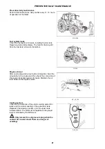
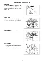
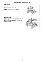
Perform this maintenance daily or after every 8 - 10 hours of operation at the latest.  


Safety cab


z

If the protective frame of the safety cab is damaged by corrosion, an accident or otherwise, the safety 

cab must be replaced.  


Air-conditioning 


z

Disassembling, turning or otherwise handling the screw union of the air-conditioning system is not 

allowed in any case. Sudden leak of the coolant may occur, causing quick local cooling. Contact or 

freezing of components in hands may cause serious damage of some tissues.  

z

The air-conditioning system is equipped with quick-couplers that make it possible to separate the cab 

from the tractor body if necessary without any coolant leak. Entrust interventions into the air-

conditioning system to a specialized repair shop.  

Electric installation


 No additional interventions into the electric installation (connection of other electric 

appliances) are permissible due to its possible overloading!


z

The values of the electric installation are: 


Nominal voltage 12 V = 

Grounded minus pole ( - ) pole 

z

Using starting trucks or auxiliary power supplies with a different voltage or polarity may cause serious 

failures of the tractor.  

z

When handling the battery you must pay increased attention and avoid short-circuits. In tractors 

equipped with a battery disconnector switch the disconnector off when handling the battery.  

z

Zetor tractors must not be operated with a disconnected battery as this may lead to a serious failure of 

the tractor.  


   SAFETY INSTRUCTIONS FOR USERS

16

16

Summary of Contents for FORTERRA HD Series

Page 1: ...130 140 150 Tractor is Zetor Since 1946 OPERATOR S MANUAL FORTERRA HD 01 2014...

Page 2: ...a lot of new information and get a perfect overview of how to use the tractor with maximum efficiency during various kinds of work If you observe the rules of tractor operation and maintenance and dri...

Page 3: ...2 2...

Page 4: ...ltration 23 Hitches 23 After wirk with front implements and in case of cooler clogging 23 Tyres and wheels 24 Short functional test 24 Acquaintance with the tractor 25 Safety cabin 25 Opening the door...

Page 5: ...lever 45 Gear shifting scheme 46 Pedals and levers 46 Road and reduced speeds shifting lever 46 PTO revolutions preselection lever 46 Manual brake lever and coupling for semi trailer control lever 47...

Page 6: ...rive axle control 62 Driving with engaged front axle drive 62 Manual Front drive axle control 62 Automatic front drive axle control 63 Axle lock control of rear and front axle 63 Automatic axle lock c...

Page 7: ...rol 87 Maximum transferred output 88 Drive of machines with greater inertia masses 88 Hydraulic system 89 Hydraulic system 89 Indication of low oil temperature 89 Hydraulic pump 89 Control elements pl...

Page 8: ...nt drive axle in tractors equipped with non removable discs 111 Toe in of the wheels of the front driving axle 111 Adjustment of toe in of the wheels of the front driving axle 112 Front drive axle fen...

Page 9: ...ir cleaner maintenance instructions 137 Recovery of the mainair cleaner element 137 Replacing the safety element of the air cleaner 137 Reassembly of the air cleaner elements 138 Hydrostatic steering...

Page 10: ...5 Permitted maximum load of front axle kg 156 Permitted maximum load of rear axle kg 156 Permitted maximum weight of set tractor mounted machine kg 156 Manoeuvrability condition 156 Front tires steera...

Page 11: ...NOTES 10 10...

Page 12: ...r 4 Tractor serial number When ordering spare parts and within all written and oral communication always specify the data of your tractor that should be written in the frames below Tractor type Tracto...

Page 13: ...The right left front and back indications refer to the driving direction of the tractor F11N003 LOCATION OF SERIAL NUMBERS 12 12...

Page 14: ...mbol refers to optional tractor accessories installed by the manufacturer on the customer s request Instruction manual s passages related only to models equipped with DPF diesel particle filter are la...

Page 15: ...plate of the tractor or on the rear wheel mudguard z Do not use the differential lock when driving into a bend z It is forbidden to get into and out of a moving tractor z When driving with machines a...

Page 16: ...the side plates of the hood it is always necessary to stop the engine The tractor engine can only run in a closed building or room if sufficient ventilation is ensured Exhaust gases are harmful for he...

Page 17: ...b is damaged by corrosion an accident or otherwise the safety cab must be replaced Air conditioning z Disassembling turning or otherwise handling the screw union of the air conditioning system is not...

Page 18: ...pean directive 2009 63 EC Amendment VI UPOZORN N Transportation of personnel on front passenger s seat is allowed only with road transportation Transportation of front passenger outside the seat desig...

Page 19: ...cts It is necessary to observe applicable local valid regulations in countries which are not part of the European Union Two types of cab roofs are mounted to Zetor tractors 1 Standard cab roof 2 Cab r...

Page 20: ...erve special instructions related to accidents prevention and general rules related to technical safety la bour medicine labour hygiene and regulation defining operation on roads z The manufacturer do...

Page 21: ...tective Structure Operator Protective Structure tested according to standards for forest machines Only forest superstructures approved by ZETOR TRACTORS can be mounted to ZETOR tractors In case of add...

Page 22: ...dip stick check the oil quantity in the engine and then check the connection of the engine lubrication system for leaks Maintain the oil level between the dipstick marks XF_02_193 Check the connectio...

Page 23: ...k the air system of the brakes for leaks and the efficiency of the tractor brakes with a trailer see the Maintenance instructions chapter the Checking the air systems for leaks section of this Operato...

Page 24: ...moving the covering grills in the roof overhang At the customer s request we supply filters with active carbon Don t clean the filter don t flush it with compressed air F_02_9 Check the condition of t...

Page 25: ...Check and if necessary retighten the bolts of the front and rear wheels Never drive with loose wheel bolts F11006 After starting the engine check whether the hydrostatic steering failure engine lubri...

Page 26: ...Lever for opening the door from the inside 2 Lever for opening the door from the inside The door is held by a gas strut with a full opening Driving with open door is not recommended for their possibl...

Page 27: ...ol panel for more see ELECTROHYDRAULICS chapter 4 External hydraulic circuits outlets control panel for more see HYDRAULIC EQUIPMENT chapter 5 Manual gas lever 6 Starter 7 Three pin socket The window...

Page 28: ...Rear PTO shaft switch 7 Rear PTO shaft revolutions selection switch 8 Automatic disengagement of rear PTO shaft clutch switch 9 Multiplier pre selection switch 10 Not engaged Front wiper speed switch...

Page 29: ...ont window is automatically wiped The number of wipes depends on the length of time the washer is used FHD14N024 Passenger s seat is tiltable and placed on the left mudguard of the cabin FH12N020_1 Pa...

Page 30: ...in the rear part of the cabin behind the driver s seat F31 Another shelf is placed on the right mudguard FHD14N025 Before the drive or starting the work adjust rear view mirrors so that they enable t...

Page 31: ...e controller to the lower position to lock it 8 The seat height adjustment and seat suspension adjustment according to the weight of the driver push the controller to increase the air pressure in the...

Page 32: ...given on the filter If you happen to smell pesticides in the cabin replace the filter immediately and have the sealing of the cabin checked Used filters must be damaged in specialized collection centr...

Page 33: ...a 0 ventilator off 1 slowly run of ventilator 2 medium run of ventilator 3 maximum run of ventilator F_02_16_b Do engagement and disengagement of air condition system function by switching the switch...

Page 34: ...009 Proceed accordingly 1 Turn the heating valve control A to the position on the right fully opened heating valve 2 Set air circulation in cabin control D to the position of inner circulation 3 Selec...

Page 35: ...praying pesticides and using the heating filter with active carbon the recirculation controller should be in position air is drawn into from the outside and the fan controller should be in the positio...

Page 36: ...de outlets to the side glasses of the doors as necessary and gradually defrost them After defrosting direct the outlets in such a way that the air should not be blown directly to the driver but down t...

Page 37: ...onnected 11 not connected 12 not connected 13 Indicator red of a failure in the hydrostatic control system It lights with engine operation in hydrostatic control failure If the engine is at standstill...

Page 38: ...st resetting of the data 6 Accumulator battery voltage 7 The main array machined area in hectares secondary array in hectares secondary array hourly performance i e mean machined area in hectares per...

Page 39: ...operation for more Brake the tractor by a manual brake FH12N039 Serious faults in the system 1 STOP sign number of fault 1 is displayed on a display with serious faults If this situation occurs set t...

Page 40: ...ns and press button A Select language mutation by buttons B an C and by one by one presses of button A available language mutations will be one by one displayed When achieving the desired language mut...

Page 41: ...on width menu Select the required aggregation width by B and C buttons and confirm by pressing A button Select an item 1 by B and C buttons and press A button for return to machined area a menu Settin...

Page 42: ...ing machined area will be recorded depending on the aggregation width and the travelled distance The record of the machined area will end if you select item 3 in the machined area menu b and press A b...

Page 43: ...the tractor with a stable speed of approximately 10 km h after travelling the whole distance of 100 m stop the tractor at the marked end of the track b select the item 6 by pressing the buttons B and...

Page 44: ...ts is signalized by interrupted blinking control on the dashboard F58 a roof lights on b roof lights off The switch controls the illumination in the grill or in the roof of the cabin of the tractor Us...

Page 45: ...led via the key is disconnected The key can be removed S43 The voltage is connected to all the equipment excluding starter The key is in this position with the engine running S44 Starter and supply of...

Page 46: ...s with electronical control of revolutions Reversing lever Gear shifting lever F front driving lever in the front N neutral R back driving lever at the back X212a main gear shifting lever 1 button for...

Page 47: ...the head of gear shifting lever FH12N038 1 travel clutch pedal 2 foot brake pedals joint by a catch 3 throttle pedal FHD14N083 The lever is placed on the right side of driver s seat H Road speeds N N...

Page 48: ...er can be started F74 Disconnect the battery immediately by battery disconnector which is placed on the right side of the tractor with long term standstill repairs or accident a battery connected b ba...

Page 49: ...he part of sealing of rear window in upward direction Put the aggregated tool control through the originated hole Insert cabelling or Bowden controls to the holes of passage of aggregation opening Ret...

Page 50: ...n neutral position 4 PTO switches are off If clutch pedal is not depressed the tractor cannot be started start protection switch is not switched FHD14N038 Return the key to 0 position Wait 30 second a...

Page 51: ...at 1 Insert the key to the switchbox 0 position 2 Depress the clutch pedal 3 Shift the main gear shifting lever to neutral position 4 Shift the reversing lever to neutral position 5 Make sure that all...

Page 52: ...heating first disconnect the device from the electric network and only then pull the plug out of the heater The danger of injury by electric current It is necessary to ensure instruction of the tract...

Page 53: ...e equipped with a five gear synchronized gearbox three gear torque multiplier reversing and two gear reduction Five gear gearbox is shifted by main shifting lever with buttons for disengaging the trav...

Page 54: ...ds F72 The individual positions of road and reduced speeds lever are signalized by a sign 1 in the left bottom corner of the display road speeds neutral position reduced speeds FHD14N041 The driver s...

Page 55: ...olling travel clutch with the function of automatic dead start for the regular operation of tractor with dead start gear shifting or the change of the driving direction 2 Clutch control button on the...

Page 56: ...d applicable gear followed by dead start without using the clutch pedal or clutch control buttons 1 Start the engine 2 Shift appropriate gear for starting the engine 3 Release the manual brake if you...

Page 57: ...ing the direction of the drive of tractor use reversing lever under the steering wheel without using the clutch pedal For changing the direction of the drive of tractor select the slowliest gear L wit...

Page 58: ...ng engaged and at the same time increase the engine revolutions Gear shifting using the clutch control button on the head of gear shifting lever Press the clutch control button on the head of gear shi...

Page 59: ...1 z flashing when engine is running indicates oil temperature lower than 20 C More information in chapter HYDRAULIC DEVICE z glow when engine is running indicates full pushing filter of gearbox distri...

Page 60: ...happen that some of the functions will not be complete If this situation occurs finish your work and contact service FHD14N045 With some failures of travel clutches system the function of automatic de...

Page 61: ...es the travel speed by two gears FH12N054 Multiplier pre selection switch is located on the control panel on the right rear mudguard Engaging the switch is signalized by a lit symbol on the switch If...

Page 62: ...600 and 1 900 engine revolutions necessary for automatic multiplier shifting used in this example are purely informative in practice the number of revolutions is set by the driver according to the sp...

Page 63: ...lized by blinking of control in a switch After switching off of the blinking control front drive axle is automatically disconnected With the drop of travel speed under 20 km h front drive axle can be...

Page 64: ...k control of rear and front axle FHD14N034 Axle lock control button is placed on the panel on the right rear mudguard Engagement of axle locks is done by pressing the button which returns to its initi...

Page 65: ...VE OF AGRICULTURAL MACHINES chapter when lowering the arms of the rear three point hitch the axle locks get engaged automatically 3 travel speed is higher than 15 km h with lowered travel speed the ax...

Page 66: ...locked b middle position of the button the so called manual mode Height adjustment of front drive axle works in this position by the button 2 Suspension works by the axle c after pressing the lower p...

Page 67: ...iesel particle filter which originate by burning diesel FH12N056 The activity of diesel particle filter is signalized by a pair of controls green and red on the dashboard Diesel particle filter system...

Page 68: ...ata of diesel particle filter system are displayed on the display The acoustic signal can be turned off by the button 2 If the failure has not been removed the acoustic signal is active with repeated...

Page 69: ...icles which clog diesel particle filter burn The conditions suitable for diesel particle filter regeneration are signalized by a lit green control on the dashboard Depending on the temperature of exha...

Page 70: ...ontrolled double pedalled with automatic pressure equalizer When driving on the road both pedals must be connected by valve Use disconnected pedals for braking right or left wheel only when working in...

Page 71: ...h the control valve at 600 20 kPa When connecting the trailer articulated trailer with a maximum allowed weight approved for the type of tractor at stake is a maximum allowed speed of the set of 30 km...

Page 72: ...hydraulic circuit it is necessary to bleed the hose from the brake valve to the quick coupling When driving with connected trailer or articulated trailer the pedals of foot brake must be connected an...

Page 73: ...ke 3 Wheels based by wedges Engaging a speed gear does not secure the tractor from start clutch is switched off Lock the cabin FH12N077 Hydrostatic steering pump failure is with oil pressure drop unde...

Page 74: ...sufficiencies to be removed immediately you will thus prevent subsequent damage or endangered operation z Keep the same procedure also after tractor complete overhaul In first 10 hours of operation Fr...

Page 75: ...NOTES 74 74...

Page 76: ...pins 3 Now the stage hitch is released and you can adjust its height or disassemble it When you release the lever from position 2 the locking pins 3 will extend and the lever will automatically retur...

Page 77: ...2 in the arrow direction 3 Connect the shaft lug to the fixed pin 3 4 Return the locking wedge 2 to the original position and secure it with the pin 1 D206 The console with a 80 ball is only used to c...

Page 78: ...pe Permissible vertical static load Hitch pin Hitch type Permissible vertical static load Hitch pin Hitch class C 2 000 kg 31 mm 2 000 kg 38 mm 2 000 kg 28 mm Hitch class D2 Hitch class D3 2 000 kg 43...

Page 79: ...NOTES 78 78...

Page 80: ...y be equipped with one of two systems of rear PTO shaft revolutions preselection The system used in the tractor is marked on the label placed by rear PTO shaft revolutions preselection lever 1 Standar...

Page 81: ...f the arrow C Dependent and independent rear PTO shaft revolutions FHD14N008 The system used in a tractor is marked on the label placed by the rear PTO shaft revolutions preselection lever This system...

Page 82: ...nt revolution of rear PTO shaft When manipulating with PTO shaft by means of buttons 1 the operator must stand beyond the space of the connected tools not to be caught or injured Selection switch of r...

Page 83: ...switch 1 returns to B positions By another depression of the switch 1 from B position to C position this function is disengaged Check that the PTO shaft revolutions are set properly with regard for t...

Page 84: ...olutions 3 Rear PTO shaft is set into operation by switching the switch of rear PTO shaft 3 Engagement of rear PTO shaft is signalized by the display of the number of rear PTO shaft revolutions on the...

Page 85: ...the switch 1 returns to B position By another depression of switch A from B position to C position this function is disengaged Activation of Automatic disengagement of PTO shaft clutch function is si...

Page 86: ...PTO shaft clutch ACTUAL current position of arms of three point hitch L LIMIT position of arms of three point hitch at which engagement of rear PTO clutch occurs The number with individual items has...

Page 87: ...e number by H LIMIT item must be always greater at least by 10 than the number by L LIMIT item or the new value will not be saved Beware When setting the position of arms of automatic disengagement of...

Page 88: ...TO clutch again by switch A according to previous articles Front PTO shaft Front PTO shaft control Front PTO shaft is equipped with a solid six or twenty one splined end point and it comes only in des...

Page 89: ...e 90 kW Rear 1000 per minute full engine output 540 per minute full engine output 1000E per minute 60 kW 540E per minute 60 kW F_02_46 Cardan shaft for drive of these machines must be equipped with th...

Page 90: ...ashing When the temperature of gear oil is higher than 20 C the signal lamp 1 stops glowing If the signal lamp 1 is flashing it is not recommended to use outer circuits of hydraulics The hydraulic pum...

Page 91: ...draulic system terminated with quick couplers The sockets of the rear A as well as front B quick couplers have the inner diameter of 12 5 mm and comply with the international ISO 5675 standard FHD14N0...

Page 92: ...If the tractor is equipped with front outlets quick couplers these are controlled with a control III and quick couplers A and B section III are not mounted If the tractor is equipped with an auxiliary...

Page 93: ...th the waste With maximum flow the movement of control faces an increased resistance After overcoming the increased resistance the control can be shifted to b position in which the control is locked b...

Page 94: ...c circuits controlled with controls III and IV External hydraulic circuit front outlets and front three point hitch FHD14N071 Front outlets of external hydraulic circuit are located on a panel in the...

Page 95: ...ntrolling external hydraulic circuits with the joystick is preserved Front outlets of external hydraulic circuit tractor with auxiliary switchboard for front hydraulic circuits FHD14N075 Front outlets...

Page 96: ...o the quick coupler 0 Connecting reversing hydro engine Reversing rotation hydro engine needs to be connected to quick couplers of one section for its function In this case however it is necessary tha...

Page 97: ...NOTES 96 96...

Page 98: ...speed 4 Setting the position of lifting device 5 Upper position restriction 6 Smooth setting of manual control automatic control 7 LED diagnostic 8 LED lifting 9 LED lowering 10 Engaging compensator s...

Page 99: ...arted Activation of the EHR B system is only possible when the lubrication indicator has gone off The blocking can only be cancelled system activated with the engine running by moving the lifting leve...

Page 100: ...fety the steering axle is not unloaded so much 2 Stabilization of the transported implement 3 Reduced dynamic stress of the hydraulic system and the rear three point hitch During the adjustment of the...

Page 101: ...ol of the maximum lowering speed Symbol of the minimum lowering speed F_02_170 For permanent work with free hydraulic system e g during work with a plough with a support wheel the position of the cont...

Page 102: ...2_172a Do the step according to Cancel blocking part Set the control 6 to hitchtronic AHC position By control 4 set the working depth of tools attached to rear three point hitch When the implement att...

Page 103: ...control buttons are functional also without previous activation of electrohydraulics even in case of electrohydraulics blockage for the reason of possible failure Control the arms of the rear three po...

Page 104: ...safety shutdown of the electro hydraulic system the electro hydraulic system is out of operation the work with the tractor must be stopped 1x 2x 1x 3x 1x 4x 1x 5x 1x 6x 2x 2x Moderately serious error...

Page 105: ...n 3x 2x Left dynamometric pin A Faulty contact or interrupted conductor of the dynamometric pin Short circuit of the dynamometric pin conductor Possible overloading of the dynamometric pin 3x 4x Lower...

Page 106: ...ng to ISO 37 mm of the upper draw bar opening 32 mm E451 Persons that are not authorized to work with the attached implement must not stand between the tractor and the hitched machine implement A Do n...

Page 107: ...hydraulic draw bars B The pin head 1 and washer 2 are installed vertically The free position enables free connection of the tractor and implement In this case both the draw bar ends may move freely a...

Page 108: ...int hitch Lower draw bars with CBM hooks Securing the lower draw bars with CBM hooks The lower 3 and upper 4 draw bars of the hitch are equipped with CBM hooks First suspension CBM balls 1 must be fit...

Page 109: ...the hitch must always be hydraulically locked in the lifted position with valves that are installed on the left side of the tractor over the front axle This hydraulic lock is recommended even in case...

Page 110: ...undesired pressing Switch switching a is not signalized The buttons on the upper part of the joystick are not functional The control IV is not functional in the controlling front three point hitch mod...

Page 111: ...anging the position of the draw bars of the front three point hitch 1 Release and remove the pin 1 from the opening 2 Lift the arm from position A to position B 3 Lock the arm by inserting the pin 2 i...

Page 112: ...s fixing the front wheels Toe in of the wheels of the front driving axle Front wheels track 1 924 mm Proper toe in or toe out S of front wheels in a tractor with front drive axle is measured on wheels...

Page 113: ...easurement on the sides of rims z Locking nuts of heads of ball joints 2 tighten with a torque of 122 136 N Upper surfaces of heads must be 1 parallel Front drive axle fenders Front drive axle fenders...

Page 114: ...is at least 50 mm Check both front tires 2 Turn the steering to full lock to the other side and check according to point 1 3 Heave one side of the front axle to the maximum swing front axle leans aga...

Page 115: ...NOTES 114 114...

Page 116: ...ible after removal of the battery holder Combination of weights pcs Mass of weights kg 2 2x34 68 F223 The front weights of the can type are suspended in the tool carrier They are protected from latera...

Page 117: ...or you can fill the tyre under pressure C 6 Remove the hose and unscrew the adapter for water filling 7 Screw on the valve insert and inflate the tyre to the prescribed pressure 8 After inflating scre...

Page 118: ...ized air C 4 Blow out the liquid until it stops running through the tube of the air adapter 5 Unscrew the adapter for water filling 6 Screw the air part of the valve back on and inflate the tyre to th...

Page 119: ...tion must not get in contact with metal parts and the electric installation The solution is not harmful for the tube valve 5 The antifreeze solution with the above mentioned composition must not be us...

Page 120: ...ust be in the neutral position do not forget to check whether the locked PTO switches on the right cabin pillar are off as well to prevent spontaneous start and endangering of the service person s lif...

Page 121: ...hem with soap 4 During charging hydrogen is released from the electrolyte on the electrodes Hydrogen mixed with the air forms an explosive mixture Therefore it is prohibited to handle open fire near t...

Page 122: ...oper grounding of the alternator Poles of the alternator may not be re versed even for a short time F_02_207 Is signalized by the selected display changing to a display with a symbol of a battery It i...

Page 123: ...Placement of fuses in fuse box X18 ELECTRIC INSTALLATION 122 122...

Page 124: ...10 3A Front PTO shaft F1A 15A Diesel particle filter CAN bus socket F1B 20A Controlling engine with mechanical revolutions control F11 15A Front and rear windshield wiper windshield washer F12 20A Rad...

Page 125: ...nal vertical plane passing through the headlight centre further than 30 m from the front outline of the tractor In the horizontal direction the light beams must be parallel with the longitudinal axis...

Page 126: ...V 55 60 W P 43t 2 Roof low beam headlights H7 12 V 55 W PX26d 3 Front combined headlights Turn signal lights P21W 12 V 21 W BA 15s Position lights R5W 12 V 5 W BA 15s 4 Working and ploughing lights 12...

Page 127: ...NOTES 126 126...

Page 128: ...he clogging indicator Check the oil quantity in the gearbox and final drive housing Check the oil quantity in the gear box of the front PTO Check the oil quantity in the reducers and in the box of the...

Page 129: ...cleaner element with hydraulic pump suction filter o o o o o 500 or according to the indication of full filter Replacing oil filter element with delivery filter of gearbox switchboard o o o o o 500 or...

Page 130: ...esignation Shell Donax TX BP Autran DX III Fluid 9 Esso ATF E 25131 Castrol Transmax S Elf Elfmatic G2 Syn Elfmatic G3 FINA Finamatic HP Finamatic S6726 Mobil Mobil ATF Texaco Texamatic 7045 Valvoline...

Page 131: ...2 80W GL 4 Fuchs Titan Supergear 80W 90 GL 4 GL 5 Titan Hydramot 1030MC 10W 30 GL 4 Titan Renep 8090MC 80W 90 GL 4 GL 5 MV Gear Oil LS 85W 90 GL 5 MOL Hykomol K 80W 90 80W 90 GL 5 ORLEN OIL Platinum G...

Page 132: ...er manufacturers has not been verified Fuel for Zetor engines which are equipped with diesel paricle filter Type Classification Shell retinax HD2 DIN 51825 KP 2 K 20 MOGUL LA 2 ISO 6743 9 CCEB 2 3 ISO...

Page 133: ...FE additives for greasing suspension front drive axle Position Name Number of greasing points 1 Transmission shaft clutches 2 FHD14N089 Pos no Identification No of lubrication points 1 Turning radius...

Page 134: ...in bearings 0 to 4 by version 01F Pos no Identification No of lubrication points 1 Pins of cylinders of the front three point hitch 4 02F Pos no Identification No of lubrication points 1 Pins of auxil...

Page 135: ...after a general overhaul of the main groups Run in the tractor after a general overhaul in accordance with the instructions for running in a new tractor Perform the maintenance in the same way as with...

Page 136: ...and the cleaner 2 Coat the rubber sealing with oil that you will fill the engine with and tighten the cleaner by hand When the sealing gets in contact with the block sealing tighten the cleaner again...

Page 137: ...with the new filter element check proper seating of the bowl gasket Bleed the fuel system During the cleaning and replacement of the filter elements place a suitable vessel under the engine to catch d...

Page 138: ...cleaner lid 1 G712 Remove the main element of the dry cleaner 2 by pulling If the main element is not damaged there must not be any dust on the inner side of the element recover it by blowing pressuri...

Page 139: ...of the dry air cleaner ensure proper functioning of the clogging indicator again G715 The tank is accessible after opening the hood It is found in the front part on the left side of the tractor By di...

Page 140: ...teering unit and the pipes F_02_114 10 Secure the tractor against movement and lift the front axle 11 Place an oil collection container under the working cylinder and by turning the wheels by hand pus...

Page 141: ...time is 20 s otherwise the oil in the hydrostatic steering circuit is heated up excessively Replacing coolant Proceed in the following way 1 Open the heating valve and release the pressure cap C on e...

Page 142: ...d the strainer element of the suctioning filter 2 2 After cleaning screw all the drain screws back on 3 Fill oil start the engine and let it run for approx 2 minutes 4 After stopping of the engine and...

Page 143: ...he inspection opening Solid front drive axle 3 Drain opening of the final drive housing oil 4 Filling and inspection opening of final drive housing oil after removing of the inspection screw the oil l...

Page 144: ...ifice in such a way to make the air flow direction correspond to the flow direction through the filter in accordance with the arrow on the filter The entering air must first pass through the white dus...

Page 145: ...e filter If you feel the smell of pesticides in the cab replace the filter immediately and have the cab sealing checked Used filters must be disposed of in specialized collection centres F13BN031 The...

Page 146: ...ressure must not drop by more than 10 kPa in 10 minutes Perform the leak check daily before driving with a trailer or semi trailer In case of a brake system failure or if the pressure drops below 450...

Page 147: ...r A After inflating the tyres you must put the rubber cap back on the pressure controller Recommended inflation values of the front wheel tyres The value of the permitted load bearing capacity of the...

Page 148: ...espond to the maximum travelling speed of the tractor i e in the case of radial tyres 40 km h and in the case of diagonal tyres 30 km h The specified values refer to one tyre For a tractor the max loa...

Page 149: ...od inflate the tyres to the value required for road transport In case of a longer period of inactivity of the tractor storage support the tractor and reduce the pressure in the tyres to the minimum th...

Page 150: ...ews of the AC compressor FHD14N080 The proper play between the piston rod of the brake pedals and the piston of the main cylinder is 0 5 1 0 mm 3 6 mm measured at the edge of the brake pedals with the...

Page 151: ...ke pedal and repeat the procedure until air bubbles stop escaping from the hose Foot brake check During the bleeding observe the liquid level in the compensation tank to avoid aspiration of air A Make...

Page 152: ...raked position Perform the adjustment in such a way that the self locking nut 1 of the parking brake draw bar can touch the pin 2 in the disc brake lever 3 After this basic adjustment check the operat...

Page 153: ...NOTES 152 152...

Page 154: ...llast weights Outline length with hitches without the front three point hitch 4650 without ballast weights Width over the rear fenders 2330 Height to the exhaust outlet 2766 Tractor height to the uppe...

Page 155: ...nominal speed ECE R24 kW 88 95 Fuel consumption at the nominal engine speed 2200 rpm ECE R24 g kWh 239 240 Max torque 1 480 rpm ECE R24 Nm 540 570 Inclination Mt ECE R24 41 38 Fuel consumption at the...

Page 156: ...nominal speed ECE R24 kW 88 95 103 Fuel consumption at the nominal engine speed 2200 rpm ECE R24 g kWh 239 240 246 Max torque 1 480 rpm ECE R24 Nm 540 570 578 Inclination Mt ECE R24 41 38 29 Fuel con...

Page 157: ...to the entire axle the permissible load with regard to tyres is specified in the tab Load bearing capacity of the rear tyres Permitted maximum weight of set tractor mounted machine kg Travelling spee...

Page 158: ...05 540 65 R24 2100 4200 100 2100 4200 90 2100 4200 75 480 65 R28 2100 4200 125 2100 4200 115 2100 4200 95 14 9R24 1950 3900 160 2090 4180 160 2100 4200 155 420 70R24 1900 3800 160 2030 4060 160 2100 4...

Page 159: ...40 3000 6000 120 3000 6000 95 3500 7000 110 600 65R38 3000 6000 100 3000 6000 90 3000 6000 65 3500 7000 80 Performance on rear PTO shaft Travelling speed km h diagonal radial 8 40 50 20 20 23 30 0 7 4...

Page 160: ...8 4 38 Road speeds 5 H 36 8 37 9 42 5 43 9 M 31 8 32 8 36 8 37 9 L 27 5 28 3 31 8 32 8 4 H 25 7 26 5 29 7 30 6 M 22 2 22 9 25 7 26 5 L 19 2 19 8 22 2 22 9 3 H 18 2 18 8 21 0 21 7 M 15 7 16 2 18 2 18 7...

Page 161: ...15 M 212 385 245 445 L 183 333 212 385 1 H 180 328 209 379 M 156 283 180 327 L 135 245 156 283 Reduced speeds 5 H 706 1 283 817 1 484 M 610 1 109 706 1 282 L 528 959 610 1 108 4 H 493 896 571 1 037 M...

Page 162: ...0 Track width front 1915 mm Tire size front 540 65R24 rear 1850 mm rear 650 65R38 Left Right Track diameter Without engagement of the front driving axle 11230 mm 11220 mm With engagement of the front...

Page 163: ...NOTES 162 162...

Page 164: ...t description 91 Coolant heater 50 Cooling system 21 D Dashboard 36 Dead start using the clutch pedal 56 Dead start by means of automatic dead start function 55 Dead start of the tractor 55 Dead start...

Page 165: ...box 141 Checking the oil level in the engine 135 I If you do not succeed in starting the engine 49 Ignition system disorders signalization 50 Immediately after cooling the cabin 34 Immediately after s...

Page 166: ...revolutions of rear PTO shaft 80 Starting the engine 14 Starting the engine of the tractor 50 Starting the engine with the use of coolant heater 51 Steps performed daily before the start of work 127 S...

Page 167: ...Operator s manual Forterra HD 130 Forterra HD 140 Forterra HD 150 Edition 1 100 2014 Publication No 22 22 12 786 ZETOR TRACTORS a s Department of Technical Documentation Trnkova 111 628 00 Brno 166...

Page 168: ...Made in EU www zetor com zetor zetor com...

Reviews: