INTRODUCTION
DISPLAY CASE MODELS (CONT.)
Zero Zone produces high quality refrigerated display cases using state-of-the-art components. The cases are built with the thickest
insulation in the industry and a high efficiency evaporator coil. Potential case features include:
Brushless D.C. electronic motors, PSC*, or shaded pole fan motors*
T-8 fluorescent lamps*
LED lighting
Standard-energy*, low-energy, or no-energy doors
These display cases were designed and tested using the following industry standards:
ASHRAE Standard 72-2005 — Method of Testing Commercial Refrigerators and Freezers (ANSI Approved)
AHRI 1200 — Performance Rating of Commercial Refrigerated Display Merchandisers and Storage Cabinets (ANSI Approved)
UL 471- Commercial Refrigerators and Freezers (ANSI Approved) (equipment certified by ETL)
NSF 7- Commercial Refrigerators and Freezers (ANSI Approved) (equipment certified by NSF)
DOE Compliant (All U.S. Sales)
ASHRAE 72-2005 specifies the test conditions for the equipment. It includes the ambient conditions of 75°F dry bulb and 55% RH.
It also specifies the door opening requirements for the performance test. Doors are opened 6 times in 1 hour for 6 seconds. The door
opening test period is for 8 hours during one 24-hour performance test. As an example, a 5-door case will have 240 door openings
during one 24-hour test. Consult the factory if your store exceeds these test conditions.
*Not for U.S. Sales
DELIVERY INSPECTION
These display cases were carefully factory-tested, inspected and properly packed to ensure delivery in the best possible condition.
The equipment should be uncrated and checked for damage immediately upon delivery.
DAMAGE MUST BE NOTED AT TIME OF
DELIVERY AND ALL CLAIMS FOR DAMAGES MUST BE FILED WITH THE TRANSPORTATION COMPANY - NOT WITH ZERO ZONE.
The carrier will supply necessary report and claim forms.
PACKAGING
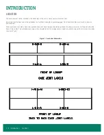
Each case in a lineup is labeled to identify the lineup and joint. The label uses a number and letter designation. The number indicates
the lineup. The letter indicates the case joint. Case joints begin with the letter A at the left most joint in the lineup when looking at the
front of the lineup. The joint for two cases has the same number-letter designation (
unique designation. The left most joint in the lineup when looking at the front of the case is labeled 1-A. The joint on the back of the case
is 1-A1 (
).
Insulated dividers are factory installed to separate low and medium temperature cases. They are also used to join different case models.
Factory installed plexiglass dividers separate refrigeration circuits.
The first case in the lineup (with the right side labeled “A”) has a packet attached to the door handle that contains the manual, special
instructions for installing ordered options, and touch-up paint if the cases are custom painted. Every case in the lineup has a packet
attached to the door that contains the specific information for that case. The packing slip is taped to the right-hand door of each case.
Bumpers and kickplates are shipped on top of the case. Shelves for the case are tie-wrapped and blocked into the individual cases. Other
accessories like drain traps, drain pans, condensate evaporation pans, and hat channels are shipped in the case that require the parts.
Materials for joining cases include caulk, joining bolts, splices, and T or J strips. These parts are supplied in cases that have a left-side
insulated divider or no left end. The parts are bagged and taped to the coil covers. The T and J strips are tied to the shelves.
Introduction • 3
Summary of Contents for 3RMCC30WA
Page 2: ......
Page 4: ......
Page 36: ...ELECTRICAL LOW TEMP Figure 26 Electric Defrost 30 24 Wiring 32 Electrical Low Temp...
Page 37: ...ELECTRICAL LOW TEMP CONT Figure 27 Hot Gas Wiring Electrical Low Temp 33...
Page 38: ...ELECTRICAL LOW TEMP CONT Figure 28 Single Point Wiring 34 Electrical Low Temp...
Page 39: ...ELECTRICAL LOW TEMP CONT Figure 29 Master Satellite Wiring Electrical Low Temp 35...
Page 40: ...ELECTRICAL MEDIUM TEMP Figure 30 RVCC30 and RMCC24 Wiring Diagram 36 Electrical Medium Temp...
Page 41: ...ELECTRICAL MEDIUM TEMP CONT Figure 31 Single Point Wiring Electrical Medium Temp 37...
Page 42: ...ELECTRICAL MEDIUM TEMP CONT Figure 32 Master Satellite Wiring 38 Electrical Medium Temp...


