


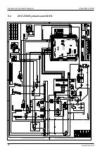


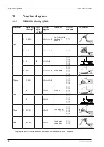


ZHD 2500-130/150
Temporary operation of lift
33
www.zepro.com
7
Temporary operation of lift
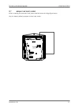
When the lift is installed, it is sometimes necessary to operate the lift functions in order to change the posi-
tion of the cylinders and the lift arms. To do this, the lift control card can be connected temporarily to run the
functions. To access the lift’s control card, see section "8 Hydraulic unit and control card" on page 34.
The battery charger must not be connected when operating the lift. Risk of damage.
With this connection, closing against the vehicle body does not work.
NOTE.
7.1
Connection
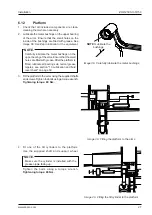
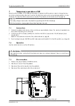
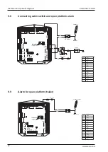
1. Connect a suitable control device to the control card, see illustration below. The number of available func-
tions varies depending on the lift model.
2. Connect an earth connection (GND) and +12/24V to the lift. See also section "16.2 Maximum power
consumption -
Minimum recommended conductor cross sectional area" on page 64.
3. Insert a jumper between CSPWR and CS to simulate a cabin switch CS in the ON position, see Image 52.
7.2
Operation
Use the control device to run the lift functions.
Take great care when running the lift functions and make sure nothing is trapped. There is a risk of injury
and damage.
m
WARNING!
7.3
Disconnection
1. Remove the jumper between CSPWR and CS.
2. Disc12-24 V from the platform.
3. Disconnect the earth connection from the platform.
4. Disconnect the control device from the control card.
Ctrl 4
Spiral
Ctrl 3
Radio
Ctrl 2
Ctrl 1
C
on
tr
l P
ow
er
Sensor Power
G
ro
un
d
IN OUT
Ai 2
Ai 1
Di 1
Di 2
Di 3
Di 4
Di 5
Di 6
PA-
PA+
CSPWR
CS
+
B
E
C
2H1
B
E
C
2H2
B
E
C
Lock
B
E
C
Lock
U
7
U
6
U
5
U
4
U
3
U
5
U
4
U
2
U
1
U
0
Ctrl 6
O
ut
In
GND
LLED
Ctrl 5
Outputs
S
en
so
rs
Up
Down
Tilt
Control voltage
Image 52. Temporary connection of lift control card
Jumper
2H