background image

18

STARTING ENGINE

The cutting head will start rotating upon the
engine starts.

1. Rest the unit on a flat, firm place. Keep the

cutting head off the ground and clear of
surrounding objects as it will start rotating upon
starting of the engine.

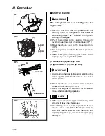
2. Push the primer pump several times until

overflown fuel flows out in the clear tube. (OP1)

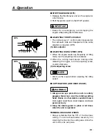
3. Move the choke lever to the closed position.

(OP2)

4. Set the ignition switch to the “start” position.

(OP3)

5. While holding the unit firmly, pull out the starter

rope quickly until engine fires. (OP4)

(1) choke lever  (2) close  (3) open
(4) ignition switch  (5) start  (6) stop

• Avoid pulling the rope to its end or returning it by

releasing the knob. Such actions can cause
starter failures.

6. Move the choke lever downward to open the

choke. And restart engine. (OP2)

7. Allow the engine to warm up for a several

minutes before starting operation.

1. When restarting the engine immediately after

stopping it, leave the choke open.

2. Overchoking can make the engine hard to start

due to excess fuel. When the engine failed to
start after several attempts, open the choke and
repeat pulling the rope, or remove the spark plug
and dry it.

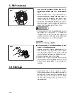
NOTE

IMPORTANT

WARNING

8. Operation

OP1

(1)

(2)

(3)

OP2

(4)

(5)

(6)

(4)

(5)

(6)

BCZ3000S

BCZ3000SW

OP3

OP4

Summary of Contents for BCZ3000

Page 1: ...s product contains chemicals known to the State of California to cause cancer birth defects or other reproductive harm WARNING Before using our brushcutters please read this manual carefully to unders...

Page 2: ......

Page 3: ...e followed in order to prevent accidents which could lead to serious bodily injury or death This mark indicates instructions which must be followed or it leads to mechanical failure breakdown or damag...

Page 4: ...ON RZ7C Fuel tank capacity 24 3 fl oz 0 72 Transmission Centrifugal clutch Rigid driveshaft Reduction ratio 1 462 Cutting head rotating direction Counter clockwise Operator view Durability period EXTE...

Page 5: ...ng label peel off or become soiled and impossible to read you should contact the dealer from which you purchased the product to order new labels and affix them in the required location s Never modify...

Page 6: ...CE PERIOD CATEGORY A ENGINE FAMILY 3KZXS 0294NO EM ENGINE DISPLACEMENT 29 5cc REFER TO OWNER S MANUAL FOR MAINTE NANCE SPECIFICATIONS AND ADJUSTMENTS MANUFACTURED Aug 2003 Use RedMax 50 1 Oil MADE IN...

Page 7: ...ou should wear proper clothing and protective equipment 1 Helmet 2 Ear protectors 3 Protection goggles or face protector 4 Thick work gloves 5 Non slip sole work boots 2 And you should carry with you...

Page 8: ...te the product properly and in a safe manner 2 When planning your work schedule allow plenty of time to rest Limit the amount of time over which the product is to be used continuously to somewhere aro...

Page 9: ...tting attachment is properly installed and securely fastened 4 Use the guard which is suitable for the cutting head If the cutting head is the metal blade change the guard In case of BCZ3000S handle a...

Page 10: ...art than the width of your shoulders so that your weight is distributed evenly across both legs and always be sure to maintain a steady even posture while working 2 Keep cutting attachment below waist...

Page 11: ...her part or when replacing the oil or any lubricant always be sure to use only RedMax products or products which have been certified by RedMax for use with the RedMax product 4 In the event that any p...

Page 12: ...re nearby before refueling 4 Wipe spilled fuel completely using a dry rag if any fuel spillage occurs during refueling 5 After refueling screw the fuel cap back tightly onto the fuel tank and then car...

Page 13: ...curely with two screws Tighten the screws gradually by turns CONNECTING THROTTLE WIRE 1 Remove the air cleaner cover 2 Connect the end of the throttle wire to the joint on the top of the carburetor SE...

Page 14: ...sten the clamp securely with two screws Tighten the screws gradually by turns INSTALLING HANDLE Mount the handle to the shaft tube and clamp it at a location that is comfortable to you SE6 1 About 14...

Page 15: ...ck T3246 24110 INSTALLING CUTTING HEAD SE10 1 While locking the gear shaft by inserting the supplied tool into the upper holder on the gear box loosen and remove the hexagon nut left handed 2 Fit the...

Page 16: ...he engine HOW TO MIX FUEL Pay attention to agitation 1 Measure out the quantities of gasoline and oil to be mixed 2 Put some of the gasoline into a clean approved fuel container 3 Pour in all of the o...

Page 17: ...R YOUR ENGINE LIFE AVOID 1 FUEL WITH NO OIL RAW GASOLINE It will cause severe damage to the internal engine parts very quickly 2 GASOHOL It can cause deterioration of rubber and or plastic parts and d...

Page 18: ...ine fires OP4 1 choke lever 2 close 3 open 4 ignition switch 5 start 6 stop Avoid pulling the rope to its end or returning it by releasing the knob Such actions can cause starter failures 6 Move the c...

Page 19: ...the cutting head keeps rotating after releasing the trigger turn the adjusting screw counter clockwise 1 idle adjusting screw Warm up the engine before adjusting the idling speed CUTTING WORK LINE HE...

Page 20: ...load on the arm and hands 6 Take precautions to avoid wire grass and dead dry long stem weeds from wrapping around the head shaft Such materials can stall the head and cause the clutch to slip resulti...

Page 21: ...washers are in place 6 While holding the spool against the housing pull the line ends to release them from the slot 7 Line up the slot on the bottom cap with the hook on the housing press the cap aga...

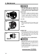
Page 22: ...the fuel filter for blockage MA3 1 fuel filter SPARK PLUG Starting failure and mis firing are often caused by a fouled spark plug Clean the spark plug and check that the plug gap is in the correct ran...

Page 23: ...SE MA6 The reduction gears are lubricated by multipurpose lithium based grease in the gear case Supply new grease every 25 hours of use or more often depending on the job condition Remove the side bol...

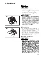
Page 24: ...ine cover shown in MA7 in order to be able to view the upper part of the cylinder If waste gets stuck and causes blockage around the intake air cooling vent or between the cylinder fins it may cause t...

Page 25: ...4 tooth SGB048 9 4 tooth SGB049 OPT1 CHOOSE THE BLADE Choose a suitable recommended cutting attachment according to the object to be cut OPT1 When replacing blade always be sure to use products which...

Page 26: ...6 43 5 in lbs TIGHTENING TORQUE 2 94 4 9 N m 1 Guard T3246 24110 BCZ3000S Change the loop handle to the J handle for safe operation OPT4 1 Bracket 3583 14101 2 J handle 6367 14200 BALANCE UNIT 1 Put o...

Page 27: ...tting depth according to the condition of object If the grass or other object gets caught in the blade or if the unit starts to shake or vibrate turn off the engine and check the whole unit Change the...

Page 28: ...d then suddenly move or bounce away from the object that was hit The operator can lose control of the unit and the blade can cause serious personal injury to the operator or any person nearby if the b...

Page 29: ...nd balance MAINTENANCE BLADE Check the blade and the fasteners for looseness cracking or bending Check the cutting edges and reform with a flat file Point OPT10 1 Keep the end corner sharp 2 Round the...

Page 30: ...GAP 0 6 0 7mm spark plug disconnected retighten Case 2 Engine starts but does not keep running Hard re starting CHECK PROBABLE CAUSES ACTION fuel tank incorrect fuel or staled fuel drain it and with c...

Page 31: ...t then use parts number described in the parts list 4 The contents described in the parts list may change due to improvement 5 The parts for the machine shall be supplied seven 7 years after the machi...

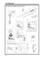
Page 32: ...12 Parts list 32 Fig 1 DRIVE UNIT BCZ3000S S N 300001 and up...

Page 33: ...10 10 E RING 1 32 T3002 12220 CORD A 1 33 T3002 12230 CORD B 1 34 T3002 12240 TUBE 1 35 T3002 83100 CABLE C 1 36 T3300 17202 HANGER C 1 37 848 805 2000 SCREW TORX 5x20 1 38 848 JC0 90R1 NAME PLATE 1 3...

Page 34: ...12 Parts list 34 Fig 2 DRIVE UNIT BCZ3000SW S N 300001 and up...

Page 35: ...ANDLE R C 1 31 6234 14601 LEVER A 1 32 6234 14601 02 COVER E54135700811 1 33 6110 14410 06 SHAFT 1 34 6110 14410 09 BUTTON 1 35 6110 14410 08 SPRING 1 36 T3002 95710 CORD A black 1 37 T3002 95720 CORD...

Page 36: ...Fig 3 ENGINE UNIT BCZ3000S S N 300001 and up BCZ3000SW S N 300001 and up 36 12 Parts list...

Page 37: ...62 T1590 31100 HOUSING C 1 63 T1590 31110 HOUSING 1 64 T1700 31212 BRACKET A 1 65 T1700 31221 BRACKET B 1 66 T1700 31232 CUSHION 1 Key Part Number Description Q ty 67 T1590 31120 DRUM 1 68 04065 02812...

Page 38: ...sibilities As the small off road engine owner you are responsible for the performance of the required maintenance listed in your owner s manual KOMATSU ZENOAH recommends that you retain all receipts c...

Page 39: ...PART THAT IS EQUIVALENT IN PERFORMANCE AND DULABILITY MAY BE USED IN NON WARRANTY MAINTENANCE OR REPAIRS AND SHALL NOT REDUCE THE WARRANTY OBLIGATION OF THE COMPANY THE COMPANY IS LIABLE FOR DAMAGES...

Page 40: ...ut tre utilis e pour l entretien hors garantie ou les r parations hors garantie et ce sans r duire l obligation de garantie incombant la soci t La soci t sera tenue responsable des dommages aux autres...

Reviews: