IRSC Plus
Technical Support:
5
Once the controller is provided with power from the KNX bus, both the physical
address and the associated application program may be downloaded.
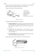
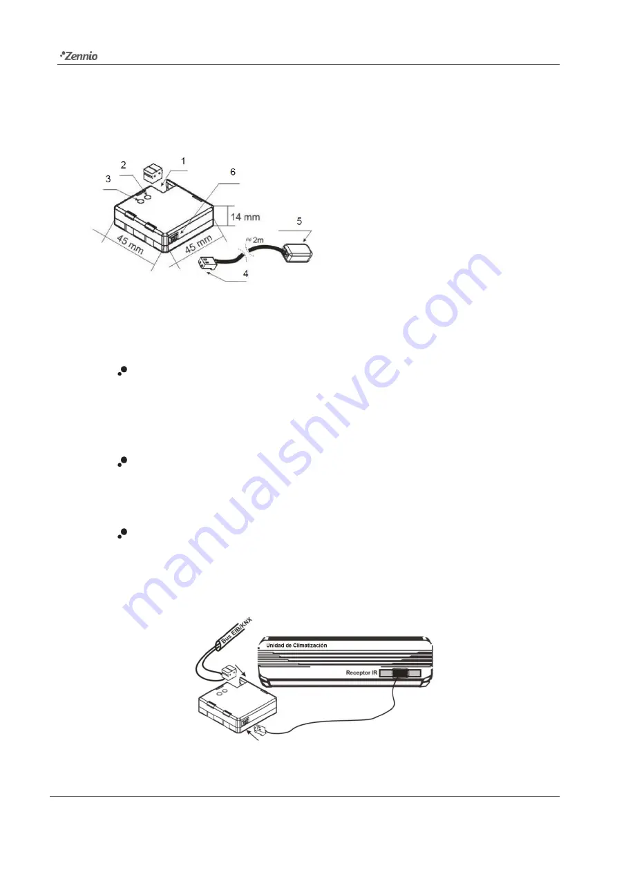
In Figure 2, the connection scheme of IRSC is shown.
Figure 2.
Element Diagram
The functionality of the main elements is described next.
Programming Button (3)
:
a short press on this button sets the device into
the programming mode, making the associated LED (2) light in red. If this
button is held while plugging the device into the KNX bus, IRSC goes into
safe mode.
IR emitter (5)
:
infrared flashing diode to send commands to the air
conditioning system. It must be placed in front of the air conditioning IR
receiver (see Figure 1.3).
Air connector Base (6)
: slot for the insertion of the aerial connector, through
which the IR commands are outputted from IRSC.
Figure 3 shows how to locate the IR emitter (5) in front of the climate system.
Figure 3.
IRSC - A/C Unit Interface
1.- KNX Connector.
2.- Programming LED.
3.- Programming Button.
4.- Aerial Connector.
5.- IR Emitter.
6.- Socket for the Aerial Connector.

